
TIP Playbook for Smart Cities
Introduction
Executive Summary
This playbook is an output of the Smart City Connectivity sub-group within the Telecom Infra Project (TIP) mmWave Networks Project Group. It’s the result of a collaboration between TIP Members —operators, infrastructure providers, system integrators, and equipment vendors—to provide guidance to key audiences (especially municipalities) about the deployment of communication services at the street level. Collaborating in TIP, we aim to streamline and accelerate network deployments.
The members of the TIP Smart City Connectivity sub-group are collaborating to address several of the major friction points in the deployment of communications equipment on street assets.
- The Integrated Hardware Asset workstream addresses aspects of equipment design, approval, and installation.
- The Best Practices workstream focuses on aspects of site identification, planning permission and permission to deploy. In both cases, our goal is to identify practical approaches to solutions rather than document the status quo.
- The End-2-End Architecture workstream creates disaggregated end-to-end network architectures for diverse use cases in urban deployments
In this playbook, we cover smart city service requirements, an overview of mmWave technology, mmWave spectrum and deployment regulation and best practices recommendations.
The mmWave sections are intended to educate infrastructure providers and cities so that they can take an informed approach to technology selection. We provide an introduction to the technology and explore different deployment scenarios. While this document focuses initially on mmWave networks technology and deployment considerations, we expect the scope to widen to include a variety of technologies that rely on network densification.
Overview
Rapid deployment is critical in creating a substantially dense network to address the smart city connectivity requirements of a population area. Wireless mmWave technologies can help accelerate deployment of the needed connectivity.
The speed and efficiency with which wireless networks can be established creates an ideal environment to provide immediate service in any given market. Deployment of mmWave technologies can be less expensive, in large part due to the minimal construction in comparison to other network technologies. Such wireless technologies can extend the reach of fiber deeper into neighborhoods and adjacent areas to make available gigabit speeds where previously not available in addition to other smart city services.
To quickly establish such networks, sufficient network density is needed. Due to low power consumption and small form factor of these new radios (often the size of a dessert plate or smaller), they no longer need to be limited to designated wireless facilities and towers. The new wireless networks can be deployed using residential or commercial rooftops, light standards, water tanks, street fixtures (e.g., light posts, traffic signals), and other vertically-oriented assets that provide line of sight to targeted facilities and residential areas.
Purpose and Motivation
The TIP Smart City Connectivity sub-group seeks to provide tools for both the network operators and public sector (government agencies) to accelerate fixed wireless network deployment. This document seeks to identify best practices and lessons learned from global fixed wireless deployments. It does so in an effort to accelerate the education and initial advocacy period with jurisdictions so as to enable faster and more affordable network deployments. Creating streamlined and consistent regulatory environments—and approval processes—enables operators to quickly deploy high-speed wireless networks to increase the availability of gigabit services and enable smart city services.
Audience
The audience for this document includes government agencies, infrastructure providers, and wireless operators looking to build or expand fixed wireless networks to service residential and/or commercial customers, or simply support smart city initiatives.
About Telecom Infra Project
Launched in February 2016, Telecom Infra Project (TIP) is a collaborative telecom community that is helping to evolve the global connectivity infrastructure. Its mission is to accelerate the pace of innovation in next-generation telecom networks through the design, building, testing, and deployment of standards-based, open and disaggregated network solutions. Over the past four years TIP has driven substantial innovation across all elements of the network including access, transport, core, and services, while spanning urban–to–rural market use cases.
If you are interested in learning more about TIP or getting involved, please visit our website.
Urban Connectivity Requirements
Smart City Applications
City governments and other local agencies have several mandates that are usually codified at the subnational (county, region, or state) or national level. These traditionally relate to cities’ role in the provision of ‘hard’ services such as utilities and public safety.
The scope has increased in recent times to include the provision of ‘soft’ services that enhance the general well-being of communities. Economic development services provide support for, and encourage growth of, the business community—in addition to increased economic engagement by each respective residential community. Digital inclusion initiatives seek to address both availability of internet connectivity and often more importantly, adoption and use of internet services throughout the community. Meanwhile, cities are expected to increase service delivery efficiency.
In support of the various services, cities deploy a number of applications that rely on broadband connectivity:
- Video monitoring: the observation of public spaces for safety purposes and transportation corridors for the management of traffic flow
- Public Wi-Fi: access in public spaces, especially where there are congregations of people in shopping and entertainment areas, transportation hubs, and parks
- Fixed broadband: high-capacity data services to residential or commercial premises
- Municipal fixed network: broadband data connections between city offices and other public agencies, such as emergency services, health services, schools, and libraries
- Municipal mobile network: service provision, typically using LTE, for field personnel and devices
- Vehicle to Infrastructure (V2I): provision for a wide range of sub-applications, from downstream/upstream data services, such as entertainment and video monitoring, to intelligent transportation systems for traffic management, to communication of telematics data to and between autonomous vehicles
- Internet of Things (IoT): smart sensor and management functions that individually don’t produce or consume large amounts of data, but in aggregate could potentially require high data capacity
Note that the delivery of some or all of these applications may depend on or be subcontracted to private entities. Substantial regional and national variations exist.
| City Services | Broadband Applications |
| Public safety & transportation | Video monitoring Vehicle to infrastructure |
| Digital inclusion | Residential fixed broadband Public Wi-Fi |
| Economic development | Commercial fixed broadband Public Wi-Fi |
| Service delivery | Municipal fixed broadband Municipal mobile network IoT |
Bandwidth Requirements
| Application | Bandwidth Allocation (Estimates) |
| Video monitoring | High definition: 10 Mbps/camera |
| 4K: 40 Mbps / camera | |
| Public Wi-Fi | 500 Mbps/access point |
| Residential broadband | 1 Gbps peak/50 Mbps sustained |
| per household downstream | |
| Commercial broadband | 50 Mbps sustained per premises |
| Municipal mobile network | 50-200 Mbps/small cell |
Connectivity Options
A number of wired and wireless technologies exist to deliver gigabit broadband connectivity:
- Fiber to the premises – Optical fiber is used to carry data from a central point to the network termination point. It typically carries a single stream of data in each direction, with the bandwidth being shared between many endpoints. This technology is most commonly found in greenfield sites, when installation cost is lowest. Fiber data capacity can be significantly increased after installation by using more complex data processing techniques and (especially) wavelength division multiplexing (WDM)—use of different light frequencies to carry parallel data streams.
- Hybrid Fiber Coax – Primarily found in residential areas, optical fiber carries data to the neighborhood and coaxial cable—originally installed for TV service—provides the final leg to each termination point. Coax can carry data at rates approaching that of current fiber deployments. Fiber will often be used in place of coax cable for ‘greenfield’ deployments.
- G.Fast – Optical fiber carries data to the neighborhood and twisted pair copper cable—originally installed for telephony—provides the final leg to each termination point. It uses complex data processing techniques to overcome the impairments of twisted pair cable, and its practical range is limited to around 100 meters. It is most commonly found in existing high-quality, well maintained networks, such as in multiple dwelling units (MDUs).
- mmWave – mmWave links are characterized by high capacity and narrowly steered short-range beams. This allows significant spectrum reuse. Data is transmitted over one or more wireless links between a neighborhood fiber point of presence (PoP) and each termination point. It’s most commonly found in a competitive service provider network, or as a complement to wired technologies in incumbent service provider networks when conditions are appropriate. The equipment is relatively inexpensive and easy to install, but must be completely replaced if greater link capacity is required.
- Sub-6 GHz – Similar to mmWave, data is transmitted over wireless links from a fiber PoP to each termination point. Compared to mmWave, these radios offer relatively lower antenna gain and steering capability (at the same form factor) and have lower available bandwidths. The non-line of sight (NLOS) transmission behavior is easier to analyze and can be more readily exploited. Sub-6 technologies are typically used to cover longer link distances (several hundred meters to a couple of kms).
It’s natural for cities to look to wired installations to provide their broadband connectivity. They usually provide the highest capacity after initial installation. Very high-capacity wireless networks can complement traditional wired networks and even be an alternative under certain circumstances.
Introduction to mmWave Connectivity
The growth of connected devices, internet streaming sites, and additional remote workers reliant upon video conferencing are just a few factors that are dramatically increasing broadband needs worldwide. In many countries, the need to access the internet has become a necessity and is increasingly seen as an essential service.
Running fiber to a facility is the ideal of providing connectivity. But deploying it can be extremely costly, as it requires substantial trenching and construction. In many areas, deploying a fiber network may simply be too cost prohibitive or not technically feasible, especially suburban, rural, and more remote areas.
The wireless industry is innovating to meet this demand. Major network operators are using wireless technologies, based on high spectrum frequencies, that provide a fiber-like experience. Fifth-generation (5G) mobile networks are being deployed globally that use a higher frequency spectrum to provide more bandwidth for mobile users. For fixed access, such high-spectrum frequencies are also being adopted to provide multi-gigabit capacity, providing customers with a fiber-like experience.
Such high spectrum solutions are known as millimeter wave (mmWave). They operate in frequency bands between 30 – 300 GHz and provide more focused and concentrated data transmission rates that are similar to fiber.
Certain mmWave spectrum frequencies can be exclusively licensed by specific operators or companies. Many of these frequency bands have been historically unused due to technological limitations. Much of this spectrum is unlicensed, so many countries are actively unlocking these higher frequencies to enable increased high-speed connectivity.
While these frequencies can provide a substantial benefit, their deployment requirements differ from lower frequency technologies. This is because mmWave requires an unobstructed line-of-site (LOS) between a transmission radio and a corresponding reception device. Due to using a higher and more concentrated frequency, mmWave signals cannot pass through solid or dense matter—including tree foliage, walls, people, and other physical obstructions. As a result, mmWave network topology needs to be of sufficient density to provide LOS to facilities (e.g., residences) and mobile devices.
To help reduce costs born from its increased density requirements, operators are rethinking their network topologies based on advancement in cloud computing and the dramatic reduction of radio costs. Specifically, graph and mesh-based networks, such as Terragraph, are being created. These enable a lower number of network distribution nodes to be deployed. They also rely on more end-user installations to expand coverage within an initial network area, as well as expand its edges. Discussion of graph and mesh-based network topologies are further discussed in section Wireless Mesh Networks.
mmWave Technology
Data Capacity
A large spectrum amount has been allocated for industrial, scientific, and medical use. Recently, global regulatory authorities have allowed (or are in the process of allowing) outdoor, point-to-multipoint and mesh wireless links as a specific use case within these bands (see section Spectrum Regulation and Equipment Certification).
Allocation of a substantial contiguous band means it can be divided into multiple wide channels. This provides for very high data capacity. For example, using IEEE 802.11ad (WiGig) channelization divides the band into channels of 2.16 GHz. Internet traffic (TCP/IP) bit rates can be achieved of up to 2.5 Gbps using 16 QAM modulation, and up to 4.5 Gbps using 64 QAM modulation.
Link Distance
The maximum distance at which a link can be reliably operated is the point where system gain (transmitter power minus receiver sensitivity) is equal to atmospheric attenuation loss. Other effects also require consideration, such as absorption by rain or reflections from objects (e.g., the ground, a building). In the 60 GHz band, loss due to atmospheric absorption is high and varies substantially across the channels. This would be an issue for long range communications. but it’s ideal in an urban setting as the frequencies can be reused across multiple links with a much lower interference risk.
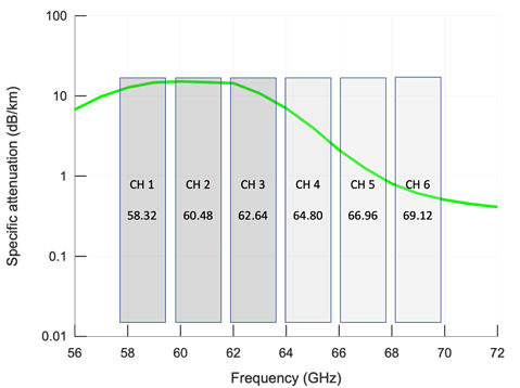 Graph courtesy of Sivers IMA
The following table shows the distance obtained for channels 2 and 6 in a 60 GHz link. It reflects some common assumptions about the required link availability and other conditions (e.g., rainfall).
| Modulation | QPSK | 16 QAM | 64 QAM |
| System Gain | 129 dB | 122 dB | 113 dB |
| Distance (Ch 2) | 330 m | 220 m | 115 m |
| Distance (Ch 6) | 420 m | 260 m | 120 m |
Table and data courtesy of Sivers IMA
Link range in channels 1–3 (57–64 GHz) corresponds to one or two city blocks. These links are ideal for creating dense urban networks where nodes are closely spaced in point-to-multipoint (PTMP) or mesh architectures. A variety of applications can benefit:
- Fixed wireless broadband – backhaul and access
- Outdoor Wi-Fi backhaul
- Small-cell backhaul
- Video surveillance backhaul
- Smart city IoT backhaul
With careful channel allocation, these links can reuse the spectrum across an urban area without causing self-interference or interference with other networks.
Some regulators have opened up channels 4–6 (64–71 GHz) for outdoor use. The ability to support longer link distances in channels 4–6 of up to 300–400 meters enhances existing applications and opens up new applications:
- Suburban and lower-density urban areas
- Lower-density small cell deployments
- Long-range video surveillance
- Wide-area smart city IoT deployments
- Transportation (roadside to bus, V2X)
It’s now possible for an operator to deploy a relatively less-dense network in the upper part of the unlicensed band. It can increase its density over time by adding new links at lower frequencies. This has the potential to significantly improve network deployment economics.
Line of Sight Propagation
Urban environments contain many objects—buildings, roadways, vehicles, trees—that influence radio frequency signal propagation. The following figure illustrates several types of indirect (or non-LOS) propagation:
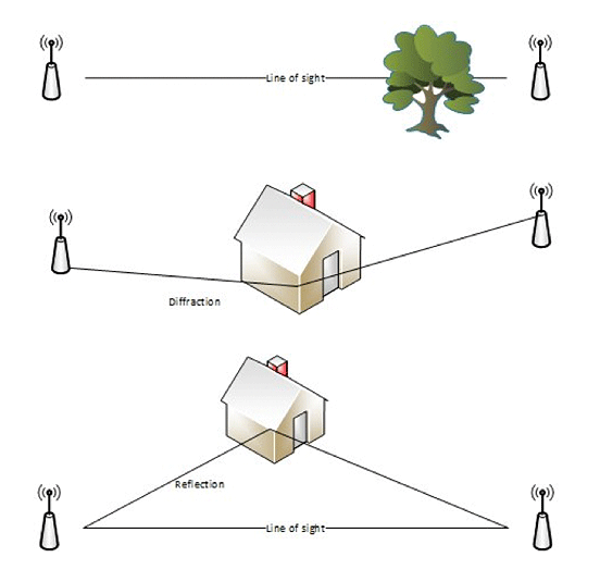
- Partial obstruction of a direct path by an obstacle, most typically tree foliage.
- Diffraction around sharp edges, predominantly buildings. Its amount is dependent on object size and signal frequency. mmWave signals diffract less than signals of a lower frequency.
- Reflection from buildings, roadways, and other less obvious obstacles (e.g., billboards, bus shelters). Note that reflectors may be artificially introduced
to provide reflection paths.
At microwave (sub-6 GHz) frequencies used by mobile cellular and Wi-Fi technologies, the propagation characteristics around obstacles are relatively deterministic. This is due to the large wavelength and as wide beams are used, coverage is relatively straightforward to predict. Traditional network planning (and the approach
of supporting tools) uses both direct and indirect paths between communication nodes.
By contrast, indirect mmWave signal propagation is heavily influenced by object size, shape, and composition. Planning analysis has shown it to be too complex and impractical for use over a large number of network links; therefore, only direct LOS paths are used.
Electronically Steerable Antennas
Transmitter and receiver gain must be sufficient to realize required link distance. Traditionally, it’s achieved at high frequencies using a parabolic dish, similar to a satellite antenna, for signal amplification.
Since mmWave antennas are very small, it’s also practical to increase gain using an antenna array instead of a dish. Electronic signals entering a transmitter antenna arrays, or exiting a receiver arrays, can be electronically manipulated so gain is higher in certain directions. Such a phased array antenna can be steered in different directions to establish links with disparate nodes; this is the basis of a mmWave mesh network.
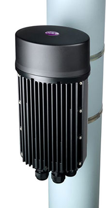
Here is an example of an antenna module that can be steered horizontally. It’s approximately 5 cm × 5 cm (2 in × 2 in):
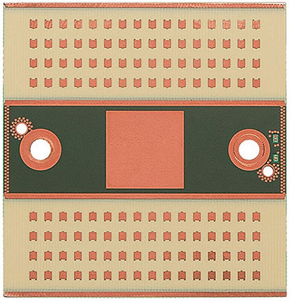 60 GHz antenna module (Courtesy of Sivers IMA)
Using a flat antenna, it’s practical to steer a beam up to 45° in each direction away from perpendicular, or 90° in total. This coverage is referred to as a sector. To provide coverage over a wider angle, for example at a 3–way or 4–way street intersection where 270° or 360° coverage might be required at a single node, multiple sectors are assembled to provide required coverage.

In the example below, a single-mesh node provides 300° coverage using four overlapping, 90° forming antenna arrays.
 Node with 300° coverage (courtesy of CCS Limited)
Reliability
mmWave reliability can be compared to fiber when the equipment is properly engineered, and radio link designed correctly.
Reliability has several aspects:
- Mean Time Between Failures (MTBF) – Regarding reliability, most commercial mmWave radios have a long working life. They’re based on highly integrated RFICs and ASICs, use a small number of components, and have low power consumption.
- Mean Time to Repair (MTTR) – Relating to the average time required to repair a failed device. Replacing a mmWave unit can be a matter of minutes or a couple of hours—significantly less than time required to fix a fiber cut. Equipment installation is simple and special mounting bracket design preserves a unit’s alignment.
- Service reliability – This parameter, the probability that a connection might be down, is related more to link design and network engineering. Usually, disparate services require different reliability.
For example, voice and management require 5 9s (99.999% annual uptime, or five minutes annual downtime). Web browsing may be delivered at 3 9s (99.9% annual uptime, or eight hours annual downtime). When installed per requirements, commercial mmWave technologies and equipment can successfully provide this reliability.
| Data Capacity | mmWave links can carry multi-gigabits of data per second, providing ample capacity for smart city applications. |
| Link Distance | High capacity links over one to two city blocks (100–200 meters) can be provided quickly and cost effectively using state-of-the-art mmWave equipment. The links can reach 400 meters where spectrum regulations allow. |
| Line of Sight (LOS) | mmWave networks are usually planned using LOS between nodes. Nodes must be located so there are no blockages from obstacles such as buildings, trees, and traffic. |
| Steerable Antennas | mmWave antenna design allows fast, dynamic switching between links—the foundation of mmWave mesh networks. |
| Reliability | mmWave links can meet reliability requirements for high availability applications, without suffering long outages associated with a fiber break. |
Wireless Mesh Networks
Mesh networks comprise nodes capable of dynamically establishing links to several other LOS nodes. In contrast to simple point-to-point links, a mesh network can switch between links according to data traffic requirements using electronically steerable antennas. This offers great flexibility in how capacity is provided. The network is generally more resilient due to multiple paths data traffic can use to cross it.
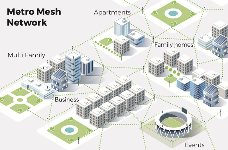 Typical urban mesh network
Distribution Links
Distribution links interconnect wireless nodes and are the backbone of such a network. Nodes are often located at intersections in a street-level installation, or at “anchor” buildings in a rooftop installation. The interval between such intersections or buildings is within 50– 200 meters. The range of mmWave distribution links in the 60 GHz unlicensed band conveniently coincides with this interval.
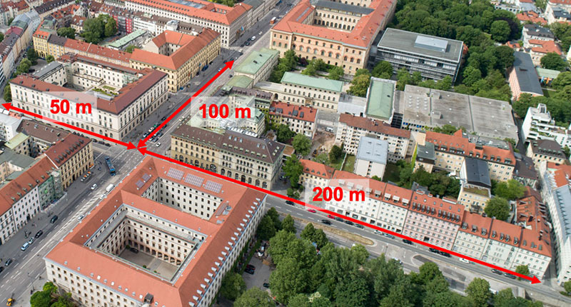 Street intersections in a dense urban environment
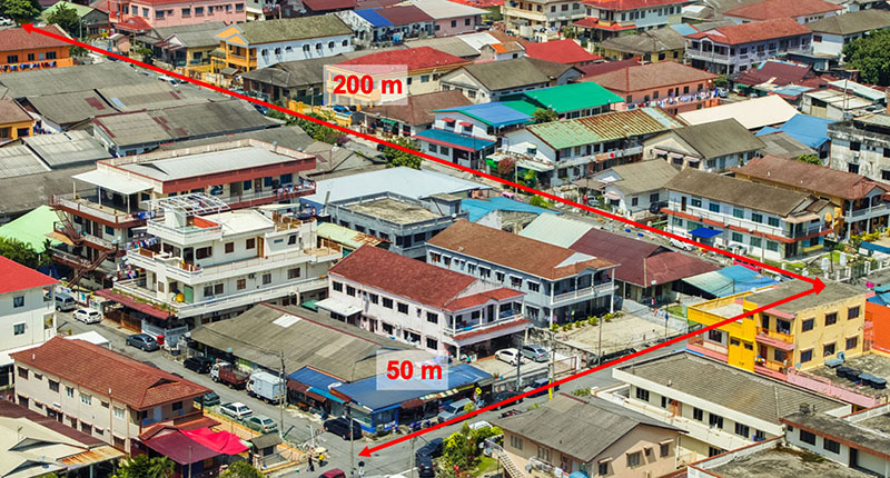 Street intersections in an urban environment
mmWave nodes at city block intervals are at similar heights and are considered to be on the same plane. An antenna array can steer horizontally between mesh network links using narrow horizontal beam widths to avoid link overlap and interference. Each link has sufficient vertical beam width to make steering in that plane unnecessary.
Access Links
Access links connect wireless distribution nodes to network termination points that are located on buildings or street assets. In contrast to the distribution network (considered as being on a horizontal plane) the access network might have significant height variations. Excluding skyscrapers in the urban core, construction regulations typically limit building heights to around 30 meters.
Typical street cross-section modeling shows that providing full building coverage from an asset across the street (illustrated below) requires a vertical steering range of 60°. Building coverage on the same side of the street requires a vertical steering range of 150°. Equipment design must account for these requirements.
 Vertical steering range of access link in dense urban setting
Fiber Points of Presence
Wireless mesh networks mitigate the need to bring fiber deep into the urban environment. But they must be connected to a fiber network at intervals for interconnection to the internet.
Several variables determine fiber point of presence density:
- Density of endpoints
- Market penetration or attach rate
- Required bandwidth
- Required latency
- Required availability or network redundancy
- Fiber installation time and cost
The required density for a wireless mesh network is anticipated to lie in the range of 1–10 fiber PoPs per square kilometer.
Based on a metropolitan area statistics survey, by comparison the number of schools per square km is in the 1–6 range. Fiber PoP and school densities are both correlated to household and population density; they should therefore scale similarly. This suggests that network plans could be designed around fiber PoP colocation at schools.
Where fiber installation to a wireless mesh node is impractical, an E-Band (71 GHz – 81 GHz licensed band) link can be used instead. Its capacity can be up to 10 Gbps in both directions, with a range on the order of several km. The ends of the link must have LOS with respect to one another.
Regulatory Framework
Spectrum Regulation and Equipment Certification
A governmental department or other state entity is responsible for the allocation of spectrum to different uses and the commercial terms for which it may be used. The International Telecommunication Union (ITU), a UN agency, works with such regulators and other interested parties to harmonize the allocation of spectrum on a regional and global level. It also develops frameworks for technical standards to mitigate interference between applications and create a wider telecom equipment market.
Under ITU auspices, spectrum allocation principles are agreed upon at the World Radio Congress. Regulators must then apply the principles in context by taking into account national law, government policy, and history. As a consequence, significant variations exist between regions and countries within them. This is particularly true of mmWave bands, which have only been addressed relatively recently.
North and South America (ITU Region 2)
| Country | Unlicensed Band(s) | Permitted Unlicensed Uses | |
| Argentina | 57–71 GHz | Indoor and outdoor use. Unlicensed for any IT or communications application within applicable technical specifications once technical rules are issued. | |
| Brazil | 57–64 GHz | Indoor and outdoor use. Unlicensed for any IT or communications application in the 57–64 GHz band within applicable technical specifications. | |
| Canada | 57–71 GHz | Indoor and outdoor use pending issuance of relevant technical standards by ISED. Currently unlicensed for any IT or communications application in the 57–64 GHz band within applicable technical specifications, extending to the full 57–71 GHz band once new technical standards are issued. |
|
| Chile | 57–71 GHz | Indoor and outdoor use. Unlicensed for any IT or communications application in the 57–71 GHz band within applicable technical specifications. |
|
| Colombia | 57–71 GHz | Indoor and outdoor use. Unlicensed for fixed wireless access systems in the 57–71 GHz band. Unlicensed for fixed point-to-point, outdoor only in the 57–64 GHz band. |
|
| Mexico | 57–64 GHz | Indoor and outdoor use. Unlicensed for any IT or communications application in the 57–64 GHz band within applicable technical specifications. | |
| Peru | None | Unlicensed operations are not permitted in the band. | |
| United States | 57–71 GHz | Indoor and outdoor use. Unlicensed for any IT or communications application in the 57–71 GHz band within applicable technical specifications. Standard: 15.255 Code of Federal Regulations Certification: FCC Authorized Test Center |
Europe, Middle East and Africa (ITU Region 1)
| Country | Unlicensed Band(s) | Permitted Unlicensed Uses | |
| Egypt | 57–66 GHz | Unlicensed for indoor WLAN operations in the 57–66 GHz band. | |
| European Union1 | 57-71 GHz | Indoor and outdoor WLAN operations pending individual state implementation of Commission Implementing Decision (EU) 2019/1345 in member states. Implementation deadline: January 1, 2020. http://data.europa.eu/eli/dec_impl/2019/1345/oj Standard: EN 302 567 with notified body opinion, draft EN 303 722 for fixed networks. |
|
| Morocco | 57–66 GHz | Indoor only. Unlicensed for indoor RLAN operations using low-power, short-range devices in the 57–66 GHz band. | |
| Nigeria | None | Unlicensed operations are not permitted in the band. | |
| Qatar | None | Unlicensed operations are not permitted in the band. | |
| Russia | 57–66 GHz | Indoor only. Unlicensed for indoor, short-range RLAN operations for devices using direct spreading and other modulations in the 57–66 GHz band. | |
| Senegal | None | Unlicensed operations are not permitted in the band. | |
| South Africa | 57–66 GHz | MGWS Indoor only. Unlicensed in the 57–66 GHz band for indoor MGWS systems. Unlicensed in the 57–64 GHz band for outdoor P2P links (but outdoor MGWS systems specifically prohibited). |
|
| Turkey 2 | 57–66 GHz | Indoor only. Unlicensed for indoor wireless access systems in the 57–66 GHz band. | |
| Ukraine 2 | 57–66 GHz | Indoor only. Unlicensed for indoor wireless access systems in the 57–66 GHz band. |
[2] Member of the European Conference of Postal and Telecommunications Administrations (CEPT). CEPT issued ERC Recommendation (70-03) on June 7, 2019. The updated general position on SRDs in the 57–71 GHz spectrum aligns with Decision (EU) 2019/1345 and permits unlicensed indoor and outdoor use, but there is no implementation deadline in the recommendation.
Asia and Australasia (ITU Region 3)
| Country | Unlicensed Band(s) | Permitted Unlicensed Uses | |
| Australia | 57–64 GHz | Indoor and outdoor use. Unlicensed for any IT or communications application in the 57–64 GHz band within applicable technical specifications. | |
| Bangladesh | None | Unlicensed operations are not permitted in the band. | |
| China | 59–64 GHz | Indoor use permitted; outdoor use uncertain. Unlicensed for fixed wireless access systems between 59–64 GHz. Regulations do not expressly provide that outdoor, fixed wireless access systems are permitted, so it is unclear whether Terragraph would be permitted. | |
| India | None | Unlicensed operations are not permitted in the band. | |
| Indonesia | 57–64 GHz | Indoor use permitted subject to publication of technical rules; outdoor use under review (February 2020). MOCI Reg 1/2019) opened the 57–64 GHz band for unlicensed use for wireless access systems, but initial technical rules will likely be for indoor use only. Authorities will likely seek further outdoor trials. | |
| Japan | 57–66 GHz | Indoor and outdoor use. Unlicensed for “low electrical power data transmitting systems” in the 57–66 GHz band. | |
| Malaysia | 57–-64 GHz | Indoor and outdoor use. Unlicensed for SRD devices operating in the 57–64 GHz band. | |
| New Zealand | 57–66 GHz | Indoor only. Unlicensed for indoor SRD systems in the 57–66 GHz band. Unlicensed for outdoor fixed P2P, but mesh configurations prohibited. | |
| Philippines | 57–66 GHz | Indoor only. Unlicensed in the 57–66 GHz band for indoor MGWS systems. | |
| Singapore | 57–66 GHz | Indoor & outdoor use permitted. But mesh networks may not qualify for unlicensed deployment due to a low power limit for outdoor applications (25 dBm) that may materially constrain mesh network operations. | |
| South Korea | 57–66 GHz | Indoor and outdoor use. Unlicensed for any IT or communications application in the 57–66 GHz band within applicable technical specifications. | |
| Thailand | 57–66 GHz | Indoor and outdoor use. Unlicensed for WLAN/WPAN operations with devices with internal antennas. Mesh configurations may be viewed as novel by the regulator and invite scrutiny. | |
| Vietnam | 57–66 GHz | Indoor only. Unlicensed for indoor wide-band communication devices (WLAN/WPAN) in the 57-66 GHz band. |
Deployment Regulation
In the previous section, we address considerations specifically related to mmWave technology. Here we examine the regulatory environment for wireless technologies in general and how they affect deployment strategy.
United States
In the US, the Federal Communications Commission (FCC) is focused on encouraging the deployment on a reasonable and timely basis of broadband services to all residents, by removing barriers to infrastructure investment and by promoting competition in broadband services. The most relevant laws and regulations that municipal leaders should be familiar with are described below.
Restoring Internet Freedom Order
The recent Restoring Internet Freedom Order reclassifies fixed wireless broadband deployment as an information service and not a telecom service (such as that of a mobile 5G provider).
Over-the-Air Reception Devices “OTARD” (47 C.F.R. §§ 1.40001 et seq.)
The Telecommunications Act of 1996 prompted the FCC to install the OTARD rule, which initially pertained to video programming. However, OTARD was further amended in October of 2000 to include antennas that receive and transmit fixed wireless signals—as used in mmWave wireless broadband deployments. From the FCC website:
“The FCC rules for Over-the-Air-Reception Devices – OTARD – protect a property owner or tenant’s right to install, maintain, or use an antenna to receive video programming from direct broadcast satellites, broadband radio services, and television broadcast stations. OTARD rules also apply to rental property where the renter has exclusive use of an area, and to customer-end antennas that receive and transmit fixed wireless signals.”
In July 2019 the FCC issued a Notice of Proposed Rulemaking (NPRM) entitled, Updating the Commission’s Rule for Over-the-Air Reception Devices (WT Docket No. 19-71; FCC 19-36). It seeks to extend protections to include hub and relay sites to reduce OTARD confusion and help advance new broadband deployments. An FCC decision to update OTARD policy is expected in the first half of 2020.
Pole Attachment Act
The federal Pole Attachment Act (47 USC §224) requires private owners of utility poles to grant non-discriminatory attachment rights to federally licensed wireless communications operators. These federal requirements are preempted in those states that satisfy the FCC that they have enacted pole attachment rules and enforce them (“reverse preemption”). It should be noted that the federal regulations do not apply to poles owned by a municipality or co-operative.
Accelerating Wireless Broadband Deployment by Removing Barriers to Infrastructure Investment
In late 2018 the FCC adopted an order entitled Accelerating Wireless Broadband Deployment by Removing Barriers to Infrastructure Investment, FCC 18-33, WT Docket No. 17-79, 85 FR 51867, which took effect in early 2019. The order has been challenged and is currently under judicial review.
The order defines small wireless facilities by objective measures while establishing substantive regulations concerning permissible fees, shot-clocks for taking action on applications, aesthetic standards, and other on-fee siting requirements.
It does not require operators to demonstrate a gap in service, in contrast to judicial interpretations of the Federal Telecommunications Act of 1996 (TCA). It also clarifies that an effective prohibition exists when a requirement materially inhibits a provider from densifying a wireless network, introducing new services, or improving existing service capabilities. Municipalities cannot condition application approval based on an applicant’s ability (or lack thereof) to prove the existence of a gap in service.
Public Health Considerations
Note: TIP is not an authority on health topics. The information contained in this section is intended to be for information only and actual implementations must conform with the regulations as established by the local jurisdiction.
All radio-based products must meet international standards that limit human RF exposure and are developed to ensure safe technology use by all. Certified mmWave products meet all national and international safety requirements, emitting signals well below international safety limits. These standards are reviewed periodically and reflect the latest scientific knowledge.
As people consider the safety of mmWave and other high frequency technologies, it’s important to understand the primary causes for concern when evaluating health risks of any antenna RF emissions. There are two relevant dimensions to assess for RF emissions: ionizing radiation and thermal heating.
- Ionizing radiation is radiation emission having sufficient particle energy to affect cells in humans and potentially cause cancer or other health issues. The frequency cutoff for ionizing radiation is 2400 terahertz (where visible light ends, and the UV spectrum begins). All of today’s communication applications (e.g., TV broadcasts, radio, mobile phones, Wi-Fi devices) operate at frequencies well below the cutoff.
The mmWave portion of the RF spectrum occupies 30–300 GHz. Practically, current mmWave technologies operate between 26–90 GHz. Even at today’s highest frequencies we’re operating at 1/30,000th of frequencies that can cause harm. Due to how radio waves work, they cannot combine to reach higher frequencies.
- Thermal heating is caused by the incidence of an electromagnetic field on a surface, such as a person’s skin or clothing. The associated measure is power density–power received over a given area. To avoid adverse health effects, governments establish exposure limits derived from scientific studies. US limits are set by the FCC, while in Europe they’re established by Directives of the European Union. In addition, the International Commission on Non-Ionizing Radiation Protection (ICNIRP) publishes guidelines for limiting exposure. The limits are separately established for (1) uncontrolled exposure to general populations and (2) occupational exposure of professionals.
| Entity | Publication | Population | Exposure Limit |
| FCC | 47 CFR 1.1310 | General public | 10 W/m2* |
| Professionals | 50/m2* | ||
| EU | 1999/519/EC | General public | 10/m2 |
| 2004/40/EC | Professionals | 50 W/m2 | |
| ICNIRP | Health Phys 118(00): 000–000; 2020 |
General public | 10 W/m2 |
| Professionals | 50 W/m2 |
*FCC regulations further specify an averaging time of 30 minutes for the general public and six minutes for professionals.
Radio technologies operate under strict regulatory limits for emissions. Where permitted (see, for example, 47 CFR 15.255 in the US and Commission Implementing Decision (EU) 2019/1345, table entry 75a in the EU), they broadcast up to ten watts (or 40 dBm) average equivalent isotropically radiated power (EIRP) in the 60 GHz band. That’s the effective amount of radio power outputted when you combine the transmitter and antenna to which it’s attached.
A safe operating distance must be calculated for each equipment type. The worst-case equipment in urban mmWave networks is the distribution node, which has the following characteristics: 6 dBm transmit power, 32 elements, 90° horizontal beam width, 20° vertical beam width. The safe distance through air at the maximum allowed operating power is:
- 0.9 meters for uncontrolled general population exposure
- 0.4 meters for the occupational exposure of professionals
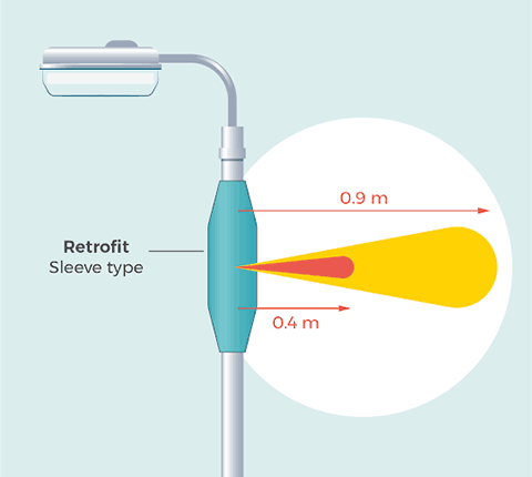 Safe operating distances for the general population (top) and for professionals (bottom) for a 60 GHz distribution node
Further, on the subject of public health, several prominent global organizations, such as the US FDA, the World Health Organization, the UK Department of Health and Social Care, and the European Economic and Social Committee have undertaken a wide range of research. It concludes there is no evidence that low-power wireless networks pose health threats to users or to the general public.
The US FCC stated in 2017 that “there is no scientific evidence that establishes a causal link between wireless device use and cancer or other illnesses.” Scientific evidence supporting this claim dates back to 2010.
The UK’s Institution of Engineering and Technology (IET) affirmed in 2014 that lack of harmful effects in research evidence from the last two years remains both reassuring and consistent with findings over the past two decades.
From the viewpoint of the UK Government Department of Health and Social Care, no negative public health effects are anticipated from the latest evolution in mobile communications technology, 5G. It states “5G will have a higher data capacity than current systems in order to transfer a larger volume of information. Some 5G technology will use similar frequencies to existing communications systems. Other 5G technology will work at higher frequencies, where the main change would be less penetration of radio waves through materials, for example walls. While a small increase in overall exposure to radio waves is possible when 5G is added to the existing network, the overall exposure is expected to remain low and well within the guidelines from the International Commission on Non-Ionizing Radiation Protection (ICNIRP)”.
A summary of the Public Health England (PHE) advice on radio waves can be accessed here. PHE has stated its commitment to monitoring the evidence applicable to this and other radio technologies and revising its advice, should that be necessary.
| Summary | |
| Ionizing radiation | Characteristic of radiation having a frequency exceeding that of visible light, such as X-ray radiation. It has sufficiently high particle energy to cause molecular changes, such as DNA mutations. mmWave radiation has particle energy of the order of 1/1000 of X-ray radiation and has no ionizing properties. |
| Non-ionizing radiation |
Characteristic of all radiation, and refers to the heating effect on an incident surface, such as skin. Radiation of sufficient power at any frequency has the potential to cause burns. Regulations establish safe distances for equipment operation. For most 60 GHz mmWave mesh network equipment operating at the regulatory power limit of 40 dBm EIRP, the safe distance is under:
These limits are the worst case in most scenarios, but the actual limits should be calculated for each type of equipment |
References and related material
47 CFR 1.1310: Procedures Implementing the National Environmental Policy Act of 1969 Section 1.1310 – Radiofrequency radiation exposure limits
1999/519/EC: Council Recommendation of 12 July 1999 on the limitation of exposure of the general public to electromagnetic fields (0 Hz to 300 GHz)
DIRECTIVE 2004/40/EC OF THE EUROPEAN PARLIAMENT AND OF THE COUNCIL of 29 April 2004 on the minimum health and safety requirements regarding the exposure of workers to the risks arising from physical agents (electromagnetic fields)
ICNIRP Guidelines for limiting exposure to electromagnetic fields (100 kHz to 300 GHz)
UK government advice on exposure to electromagnetic fields in the everyday environment, including electrical appliances in the home and mobile phones
https://www.ices-emfsafety.org/expert-reviews/
https://www.wi-fi.org/wi-fi-and-health
mmWave Network Deployment Recommendations
Roles in Urban Connectivity Provision
The key to street asset use lies primarily with municipalities. In many countries they own the streetlights, for example. They’re the financially responsible party, deciding whether and under what conditions to invest and which new applications should be explored.
In most cases, streetlight service operators help municipalities fulfil their lighting mandate. Such operators are usually public utilities or energy supply companies. Operators and municipalities work together smoothly due to tried and tested contractual relationships; rights and duties have been established for decades. Innovations are limited and can be integrated into the familiar service portfolio with comparatively little effort.
Common Ecosystem Relationship Levels
Primary Relationship: A municipality working with the streetlight service operator represents the primary relationship level in the ecosystem. For many municipalities, operators are also consultants and initiators of lighting innovations.
Secondary Relationship: The secondary ecosystem relationship level is the need for coordination within the municipalities. Here there are well established and commonly accepted principles and routines. Many municipal stakeholders are involved who have specific tasks or activity areas officially assigned to them.
Third Relationship: The third ecosystem relationship level is with external players. These include entities such as mast and lamp manufacturers, construction companies, and engineering / planning consultants.
Important Ecosystem Players
Masts and lamp manufacturers are indispensable. Masts provide access to the infrastructure which will supply future solutions. Only a few masts offer what is required for the expanded use of street lighting, as well as what municipalities accept in the way of:
- free space and interfaces for expansion modules
- independent power supply
- hidden places for applications
- organic and natural pole design (rather than grafted installations that provoke resistance)
Manufacturers of devices and systems having Smart City potential have been working on using sensors of all kinds. Sensors are used with the following to serve special municipal needs:
- traffic monitoring
- Environmental (e.g. weather) measurements
- intelligent waste containers
- cameras
- data transmission
Engineering/planning consultants support municipalities and operators with project planning. As for technical questions, check the quality of other service providers and prepare expert opinions (e.g., lighting product quality, mast statics). They’re municipal street lighting experts who cooperate directly with municipalities and know local conditions. As service providers they don’t shape the market themselves, but some might serve as advisors and have influence on given issues.
With increased use of digital solutions, intelligent lighting control, and networking, service providers and system integrators are increasingly important to municipalities and public utilities (but not so much power suppliers). The latter usually lack the know-how, personnel, and infrastructure to cope with the challenges arising from setting up and operating such systems. But at the same time, for the street lighting ecosystem this also entails costs, dependencies, monitoring, and integration requirements—a challenge for many municipalities.
Service providers are regarded as competent and financially strong. In theory, they could help close many gaps that exist among local authorities, municipal utilities, and pole and lamp manufacturers. This applies to technical topics and tasks. It also applies to the development of business models, billing systems, or (as with pole manufacturers) system management. Here, manufacturers are happy to join due to lack of strength and competence on their part.
Mobile vs. Fixed Wireless
Increased connectivity, providing more consumer choice, boosting market competition, increasing adoption , and/or providing backhaul for IoT and smart city specific applications (i.e., traffic sensors, safety cameras, water monitoring systems, etc.) are often top priorities for municipal governments. But public agencies aren’t always aware of new technologies, how they can assist in streamlining wireless network rollout, and/or how existing policies may deter market activity.
For example, fixed wireless and mobile wireless facilities are often treated by municipalities the same way, but there are important differences.
Mobile wireless systems are designed specifically to provide wireless access for mobile phones and smart devices, while a fixed wireless provider only provides broadband access to a fixed facility (and doesn’t provide voice services directly.
Additionally, mobile wireless facilities often use equipment that has a much larger form factor, along with a significantly higher power requirement. They often require multi-week construction or substantial disruption of city operations (i.e., construction and access to street fixtures in the right of way).
Municipalities are actively encouraging deployments by capping review and permit approval periods, in addition to providing set or favorable rates for monthly or annual street fixture leases. Such sites require much larger construction efforts along with equipment of larger size and power consumption. Efforts to streamline municipal processes and remove cost barriers will lead to faster rollouts and more economic deployments of mobile 5G technologies.
Today, companies benefiting most from these efforts are typically major incumbent cellular providers. They need to continue deploying many more wireless facilities to create sufficient density for mobile users. Their efforts are typically focused at high-user traffic areas or urban regions, where such technologies are deployed on street fixtures, in addition to traditional cellular towers.
In contrast, fixed wireless providers aim to provide access to specific fixed facilities and communities. Since there isn’t a moving reception target (such as a cell phone), operators can be more precise in their wireless site acquisition and deployment(s). As a result, providing fixed wireless broadband to a specific commercial area or residential community requires substantially less network density. Such service is composed of fewer, smaller, and lower-powered radios when compared to a mobile 5G network.
Fixed wireless end users are at stationary sites, so the site-mix to support such deployments can substantially differ in relation to mobile wireless providers. For instance, street fixtures in urban areas might be ideal locations for fixed wireless providers who target urban, multi-dwelling unit (MDU) buildings. Meanwhile , commercial or public rooftops might provide the ideal viewshed of a residential community in a suburban setting.
While much municipal legislation targeted at mobile 5G deployments is meant to reduce obstacles, it may have the effect of limiting deployments to specific zoned areas or specific types of assets and disallow deployment on other types of assets (i.e., “We don’t want a bunch of radios on City Hall”).
Recommendation: For municipalities to promote fixed wireless networks in line with their Smart City goals, adopting key elements of their mobile 5G initiatives should be extended to fixed wireless providers. Examples include shot-clocked permitting times for hub sites and affordable leasing rates. Additionally, municipalities should 1) examine types of sites and zoning policies that limit mobile 5G deployments, and 2) consider allowing fixed wireless providers to access these locations. (In some instances, there may be only a single site that can enable service to a community.)
Municipal Asset Inventories
It’s common for municipal assets (e.g., buildings, streetlight and utility poles, water tanks, radio towers) to be either owned, controlled, and/or managed by a variety of agencies within federal, state, and local authorities. Such traditional and non-traditional real property assets (infrastructure) are critical to their core functionality. Incumbent telecom assets have long been a common component of these assets in both wireless and wireline capacities.
Most municipalities keep an inventory of their respective real property assets through several agencies. These could include their city planning, IT, transportation, public works, and/or public safety departments, local electric utility companies, and a variety
of other agencies. This asset collection is generally (but not always) mapped by the municipality as a repository—primarily for local tax and legal offices to account for such things as revenues, taxes, depreciations, insurance, legal liabilities, public safety, and repurposing.
Rarely is there a central office in any municipality that archives, maps, and administers its collective assets for managing incumbent and/or new telecom assets—either for use on vertical structures in combination with fiber optic, or pertaining cabling infrastructure within its rights-of-way.
Yet there is a new trend, especially in the US. It mandates the collective inventory and management of municipal assets for telecom revenue generation, as well as to proliferate and accelerate the advancement of next-gen wireless and wireline technologies. An example of such a practice is in the state of Georgia. See https://gspc.georgia.gov/, with its online asset database here. An example of agencies administering the plan is found here; All of the agencies work to an even higher mandate to deploy next-gen broadband services—particularly to the state’s underserved communities.
Here is a common best practice for approaching municipalities to use their collective infrastructure for telecom deployments. First communicate to the most influential public official(s) in the jurisdiction the comprehensive goal of the deployment plan and why it’s beneficial to the public at large. Once the executive municipal authorities endorse the solution(s) benefit(s), the ease with which its real property assets can be acquired should become more fluid and apparent.
Recommendation: The best acquisition strategy, if not available through an open portal with a city agency, is to request its database and/or maps from both the top down and bottom up. Solicit city-wide, real property assets from the mayor’s office in conjunction with the GIS units of the city planning and IT departments.
Holistic Approach to Structure Selection
There are many non-traditional structures beyond right of way (ROW) street fixtures that can accommodate mmWave antenna(e) deployments. These include railway or transportation catenary, vertical pole structures, water tanks, digital signage on bus shelters, silos, high-voltage electrical structures, bridges, and port authority and industrial site infrastructure. The same set and/or sequences of traditional communications infrastructure selection, acquisition, zoning, permitting, and construction nuances apply to these site types.
mmWave deployments will converge on urban and suburban areas in large quantities from multiple operators, without coordinated colocation efforts or mandates from municipalities. Municipalities are unaware of just how much city-wide, real property assets the telecom industry seeks at the moment, as no one operator has explicitly made clear their comprehensive network plans.
As such, the use demand for critical assets to deploy mmWave equipment, such as streetlight and utility poles and other street assets, could be overwhelming for many municipalities in their effort to craft streamlined uses for hosting such equipment.
Recommendation: Municipalities should prepare for early requests for use of such infrastructure from a holistic perspective. They might provide acceptances—and possibly even master lease, license agreements, or lease options — to applicants. Specific infrastructure selection can thereafter be refined based on infield, real-world surveys.
Recommendation: Installations of mmWave equipment and an operator’s 5G equipment should be collocated—provided it doesn’t slow down their respective deployment(s) or otherwise impair competition in providing fixed or mobile broadband services. Such a partnership and practice could serve as a time-to-market accelerator, especially in markets having long lead times for leasing, zoning, and permitting.
Model Architectural Approval
Recommendation: Here is one strategy for securing and expediting leasing and permitting of streetlight pole use. Conduct a structural analysis on standard streetlights using different equipment configurations. No other equipment, such as traffic light signaling or switching equipment, signage, or other municipal appurtenances should be included.
Once it’s demonstrated that standard mmWave equipment can be accommodated by standard streetlights without other appurtenances, then the planning department might issue permits for targeted network streetlights without having to repeat this use case for each one. Additionally, this demonstration might well lead to the leasing of streetlights under a bulk or master lease agreement. Subsequent independent site lease/license agreements or SLAs might follow as the network evolves.
Beware of selecting streetlights that have a grandfathered use. That is, some might have been commandeered by public safety or DOT agencies and have equipment already collocated. Such infrastructure has often not been hosting legacy equipment in conformance with standards to which telecom equipment (i.e., mmWave antennae) is subject (e.g., structural analysis, leasing, zoning, permitting).
In such cases a selected site —having other traffic or public safety equipment already present—may require that the new applicant bring the existing structure into compliance. Here it’s possible it’s been operating, and hosting said equipment as a non-conforming structure, more often than not without the owner agency having any knowledge pertaining its specifications or dimensioning.
 Courtesy of Al Jenkins
Treatment of Terminal and Relay Equipment
Regulations such as OTARD allow the installation of antennas used to provide broadband to that facility and that meet size limitations (one meter or less in diameter or diagonal measurement) and such installation is on property that they own or rent and is within their exclusive use or control (including owners and tenants having an area of exclusive use in which to install an antenna). When providing broadband to both private and public property, therefore, many OTARD-compliant mmWave deployments should be exempt from permitting processes.
For relay or aggregation sites not explicitly covered under OTARD (e.g., cell sites, water towers), municipalities should work to ensure there aren’t undue delays or fees in the permitting process.
As municipalities begin to see more penetration of fixed broadband providers, knowledge of and compliance with OTARD regulations will help ensure the fast and affordable creation of fixed wireless networks to service their residents and support smart city programs.
Permitting and Approvals
Designing, acquiring, leasing, zoning, and permitting telecom equipment upon traditional (and particularly non-traditional) sites in rural, suburban, and especially urban marketplaces can be challenging. In most cases, all can be underestimated with respect to its time-to-market variances and obstacles.
A universal ruling from a single regulatory agency doesn’t exist for municipal mmWave equipment zoning and permitting. With respect to ease of deployment (or lack thereof), regional and/or local laws must be meticulously mapped for each domestic or international market prior to scheduling market launch or pilot plans.
The following flowchart lays out a typical permitting process:
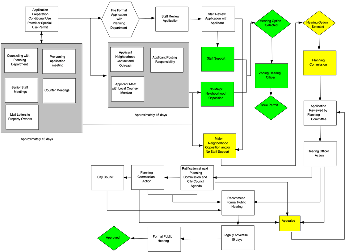
This section describes zoning and permitting best practices. These can be customized based on unique circumstances as well as local and regional deployment regulations. While they’re currently US-centric, subsequent updates will touch on EMEA, Latin America, and APAC.
Planning Staff Review Engagement
Each planning and zoning department is responsible for:
- daily administration of local community land use planning and zoning code enforcement
- counseling developers with respect to planned construction projects
- reviewing permit applications submitted by project developers
- judging the extent to which permit applications meet jurisdiction criteria (set forth in code)
- preparing and presenting staff reports and recommendations to governing authorities regarding permit applications under consideration
In many rural counties and towns, the role of “planner” could be a duty of an auditor, clerk, or other local governing post. Some small jurisdictions might have a single planner serving as the planning staff. More populated urban jurisdictions usually have a larger staff, where a number of planners perform specialized roles.
US Code Title 47 § 253(d) allows the FCC to remove state and local barriers to telecom market entry. It prescribes an ability to preempt state and local statutes, regulations, and legal requirements to the extent they prohibit the ability to provide telecom services within a state or between states. An example of streamlining permitting processes (a.k.a.,‘batch permitting) is proposed throughout several states for various technology deployments. See:
https://insidetowers.com/cell-tower-news-governor-cuomos-efforts-lauded-by-nyswa-and-wia/
However, this does not preclude a state from protecting public safety and welfare. Nor does it preclude a state or local government from managing public right-of-way by requiring fair and reasonable compensation from a telecom provider on a competitively neutral and nondiscriminatory basis—and in a manner that is publicly disclosed by such government.
Typical Timelines
Recommendation: mmWave equipment is typically smaller and therefore less intrusive than other wireless equipment. Nevertheless, a recommended best practice is to plan according to current wireless equipment leasing and permitting timelines. These are typical in each market for legacy wireless equipment located on municipal assets.
Deployment readiness can and will adjust as federal, state, and local laws adjust to streamlining these processes on a market-by-market basis for smaller form factors (such as mmWave antenna and associated equipment).
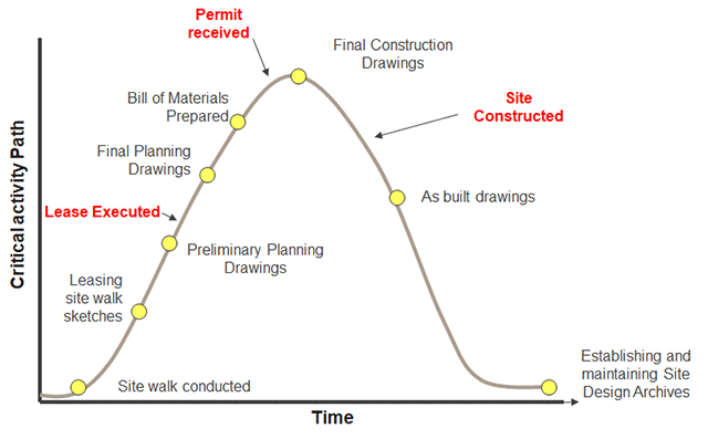
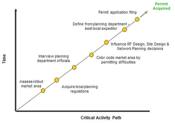
Deployment Phase
Deployment activities will consist of a variety of critical tasks in each market where mmWave and fixed wireless hubs are to be deployed—notwithstanding who may be funding the project.
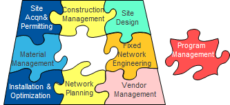
The program management team will manage several regional and local partners in accomplishing these tasks based on network design, budget, friendly landlords, and local siting ordinances, namely:
- Program/Project Management
- RF Design/Network Planning
- Site Acquisition
- Zoning Permitting
- Construction Management
- Operations & Maintenance
References and related material
- Google Fiber City Checklist, February 2014:
https://fiber.storage.googleapis.com/legal/googlefibercitychecklist2-24-14.pdf - Deloitte white paper:
https://www2.deloitte.com/content/dam/Deloitte/us/Documents/public-sector/us-ps-the-challenge-of-paying-for-smart-cities-projects.pdf - EU Smart Cities Information System white paper:
https://smartcities-infosystem.eu/sites/default/files/document/the_making_of_a_smart_city_-_policy_recommendations.pdf
City Success Cases
Publicly available deployment discussions:
-
Deutsche Telekom – DT Group and multiple operating companies
Terragraph arrives in Mikebuda, Hungary -
YTL, Malaysia
Press report about Terragraph trial led by YTL in Penang -
XL Axiata, Indonesia
Yessie Yosetya, CTO of XL Axiata, speaks to XL Axiata’s visions for Terragraph (see video at 01:05) -
Vivo, Brazil
https://www.mobileworldlive.com/featured-content/home-banner/facebook-ramps-up-terragraph-reassures-operators/ -
Claro, Brazil
https://www.mobileworldlive.com/featured-content/home-banner/facebook-ramps-up-terragraph-reassures-operators/ -
Liverpool testbed, DCMS, UK
UK government-funded test network providing digital health and social care equipment via 60GHz FWA equipment. Network comprised of 80 Blu Wireless nodes currently, expanding to 350 in next phase
http://liverpool5g.org.uk/faqs -
Cambridge Communication Systems, UK
Ontix deploying a CCS metnet 60GHz Self organizing network to supply broadband service in the City of London , UK.
https://www.ontix.co.uk/news-press/ontix-switches-gigabit-broadband-service-soho/ -
Micronat showing deploying of the CCS metnet 60GHz Self organizing network in Sweden
https://www.youtube.com/watch?v=70_GQwh8WnE -
60GHz mmWave trial to deliver capacity to an augmented reality experience
to Roman bath visitors in Bath
https://www.ccsl.com/news-events/2018/dec/13/ccs-60ghz-mmwave-trial-goes-live-city-bath-deliver/
© Copyright 2020, Telecom Infra Project, Inc.
See the TIP Document IPR Policy for the Document License details