
Network as a Service (NaaS) PlayBook
The NaaS PlayBook is the vehicle to serve as the planning and implementation guide for RST NaaS initiatives.
The PlayBook aspires to…
The PlayBook will…
The NaaS PlayBook is the vehicle to serve as the planning and implementation guide for RST NaaS initiatives. It consists of Frontend and Backend streams comprised of modules, atomic units built around specific objectives and select content and complemented by methods to encourage engagement relevancy.
1. Strategy and Design
A Strategy & Scope Definition plays a critical role for NaaS operators as it defines the strategic goals as well as the strategic decisions to achieve them.
The Strategy & Scope definition is fundamental in the NaaS operator initiative as it provides a sense of direction and outlines measurable goals. Through an optimal definition of these aspects, the leadership team can ensure alignment on the scope and priorities towards fulfilment of the strategic objectives.
This module guides the NaaS operator through an overview of the Strategy & Scope fundamentals and the imperative of its optimal definition and implementation. Furthermore, it provides an Implementation Process that can be tailored to translate the NaaS operator mission and vision into strategic objectives that can be tracked.
The main outputs of this module are the Strategies Definition for critical aspects of the Naas operator. These strategies direct the decisions on subsequent modules in order to align them with the high-level objectives. Complementary outputs are, among others, the Mission & Scope Definition and the Tracking Methodologies to evaluate the implementation of the defined strategies.
1.1 Module Objectives
This module will enable the NaaS Operator to define the Strategy & Scope of the NaaS initiative. The specific objectives of this module are to:
- Provide procedures to enable NaaS operator to perform a self-assessment analysis based on an examination of the particular environment and market.
- Guide the NaaS operator to clarify the high-level scope by defining its own tailored mission and service definition.
- Instruct the NaaS operator in the strategy and long-term objectives definition to guide decisions in downstream activities.
- Provide methodologies to control and manage the defined strategies implementation and updates.
1.2 Module Framework
The Module Framework in Figure 1 describes the structure, interactions and dependencies among different NaaS operator areas.
Strategic Plan & Scope is the first stream to build the NaaS operator. The modules in this stream aim to drive strategic decisions that impact all the downstream streams and modules. From this point, High Level Network Architecture can be defined establishing the guidelines for Network Design which in turn kick-starts the deployment phase.
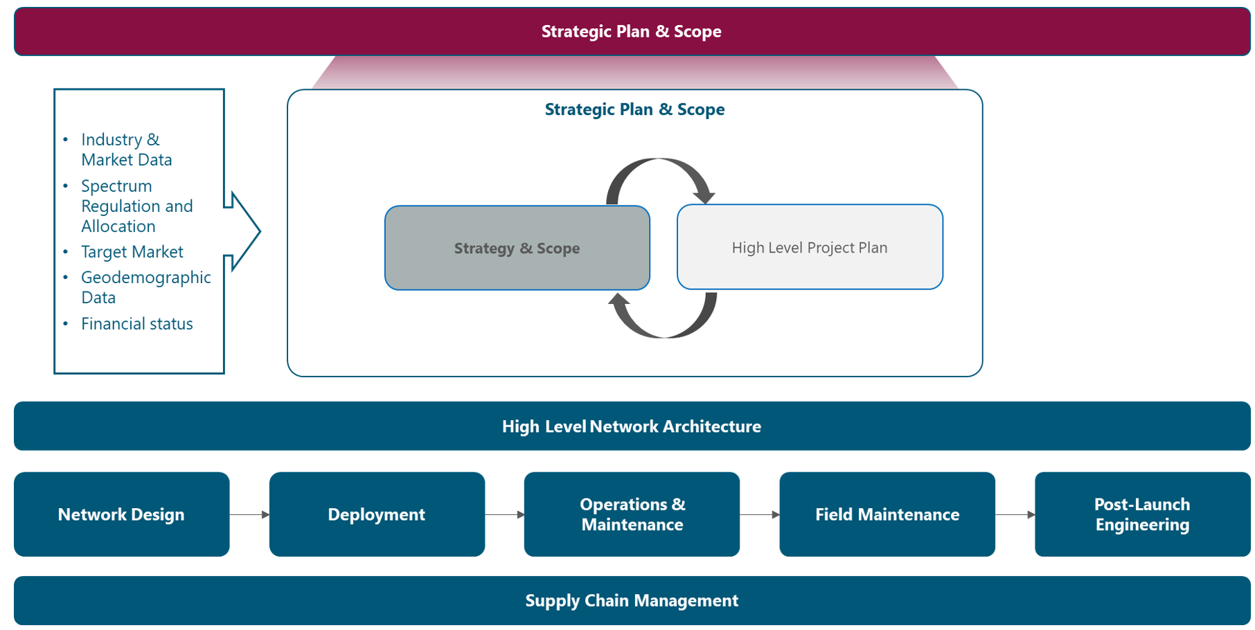
Figure 1. Module Framework
Figure 2 presents the Strategy & Scope process view where the main functional components are exhibited. Critical module inputs are further described and examined.
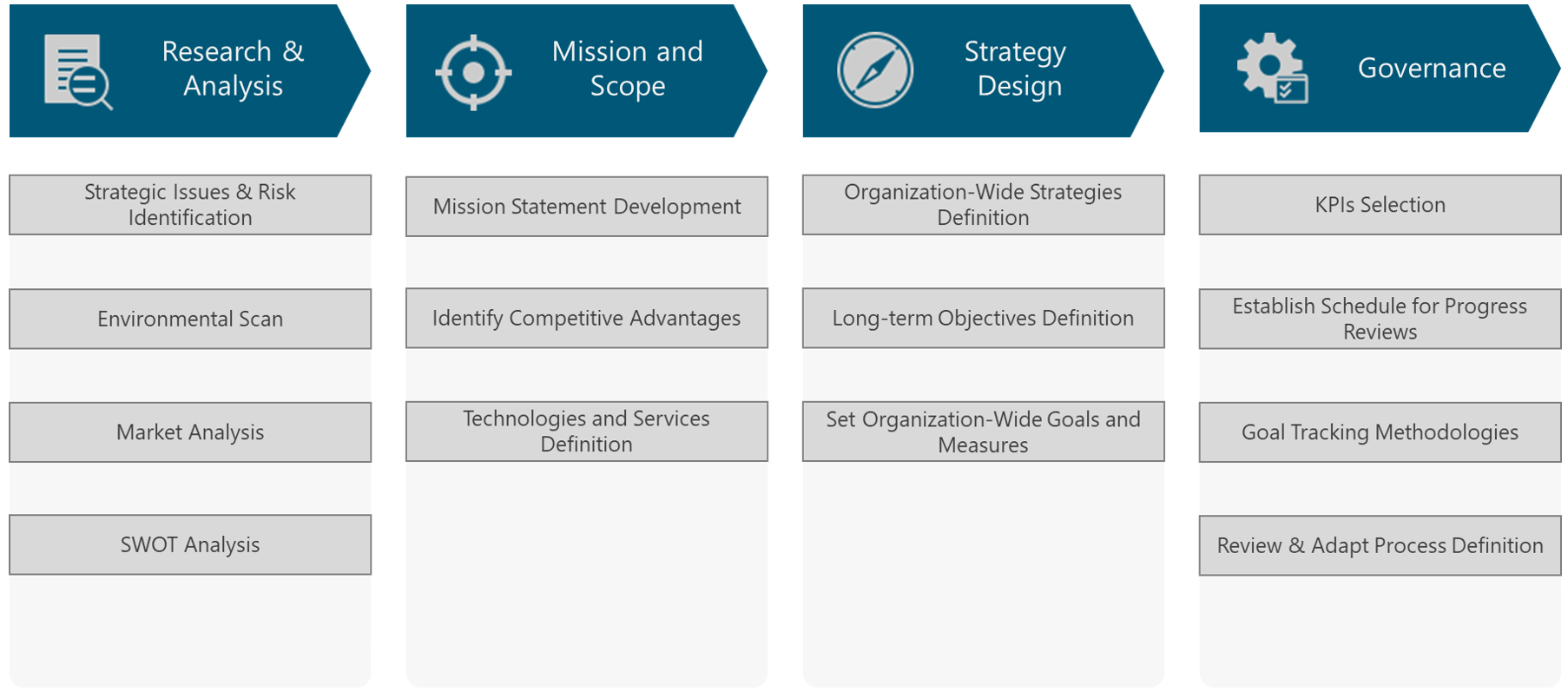
Figure 2. Module Process View
The rest of the module is divided into five sections. Section 2 is a birds-eye view of the Strategy & Scope Fundamentals as well as a high-level view of their development process. Section 3 focuses on the procedures to examine the particular environment and market. Section 4 describes processes to define the NaaS operators mission and scope. Then in section 5, methodologies to generate the overall strategies and long-term objectives are provided. Finally, Section 6 includes procedures to control and manage the implementation and updates of the defined strategies.
2. Strategy & Scope Fundamentals
This section presents a general overview of the baseline concepts to develop the NaaS Initiative Strategy & Scope.
2.1 Strategy & Scope Imperative
The Strategy & Scope of the NaaS operator is the process of an organization deciding their corporate direction, objectives and priorities, and then aligning their resources to accomplish the actions necessary to meet them.
The main outcome of the Strategy & Scope module is the Strategy definition around certain critical areas within the NaaS operator. The Strategies will guide the decision of subsequent phases (e.g. Network Design and Deployment). This means that the Network Design and Deployment streams use the strategic decisions of this module to generate its own processes. For this reason, Strategy & Scope is the first step to build the NaaS operator.
Additional outputs from this module are Organization Strategies and Long-Term Strategic Objectives. These outputs are the starting point and provide a general guide for the High-Level Project Plan, which aims to answer how the Strategy and Objectives will be achieved and who must do what to accomplish them.
Finally, as stated before, the Strategy & Scope module establishes the direction of the NaaS operator, including the financial resources, so it maintains a relationship with the Financial Plan. In other words, the Financial Plan outlines the allocation of financial resources to reach the broad goals set out in strategic planning. However, the Financial Plan is out of the scope of this module.
2.2 Process Overview
Figure 3 displays the process to develop the Strategy & Scope Definition for NaaS operators in a logical and well-structured sequence. It offers a roadmap for functional leaders that must identify and prioritize initiatives at a functional level.

Figure 3. Strategy & Scope Definition Process
The first step, Research & Analysis, provides the methodologies to analyze the conditions of different environments that the NaaS operator is subject to. This information can be collected via web research on the operating environment and telecom-industry environment reports. The survey application on customers is also a common practice. The primary outcome of this process is the SWOT analysis.
The next step, Mission and Scope, addresses the what (mission) and where does the NaaS operator want to be in the long term (vision) of the NaaS operator. The definition of these elements is an essential part to building the strategic foundation and developing a strategy. Based on these elements, the competitive advantages can be identified. An additional step for the NaaS operator, is to define the technologies and services that will be part of its catalog.
The Strategy Design step contains the methodologies to develop the strategies around different NaaS operator areas. These strategies guide the decisions on subsequent modules. Furthermore, it provides the methods to transform these strategies into realistic goals.
Finally, the Governance step provides guidance to move a strategic plan from a document that sits on the shelf to actions that drive organizational growth.
3 Research & Analysis
This section aims to describe procedures to examine the particular NaaS operator environment and market.
3.1 Strategic Issues & Risk Identification
Strategic issues are critical unknowns that need to be resolved by the strategic planning process. These issues can be problems, opportunities, market shifts or anything else requiring special consideration by the NaaS operator.
Strategic issues are developed and identified based on input from the leadership team. These issues should be a summary of critical topics that need to be addressed during the planning process. The idea is to call these issues out early, so the important areas are not lost among a lot of data, details, and ideas.
In the NaaS operator context, some strategic issues can be:
After identifying the Strategic Issues, they need to be recorded into the Strategy & Scope Definition Template as they will be used for the Strategies definition.
3.2 Operating Environmental Scan
The environmental conditions have a significant impact on the direction of the NaaS operator. Since the environment is prone to continuous changes, the organizations that are not aware of their business environments are likely to fail.
The environmental scan is the process of identifying, collecting and evaluating information about elements that are external influences on the NaaS operator. This process helps in a greater understanding of environmental changes and guides decisions on the NaaS operators strategic direction.
The environmental factors impacting the strategic planning can be grouped into two broad categories: the Operating Environment and the Telecom Industry Environment as shown in Figure 4. This section focuses on analyzing the distinct aspects regarding the Operational Environment.
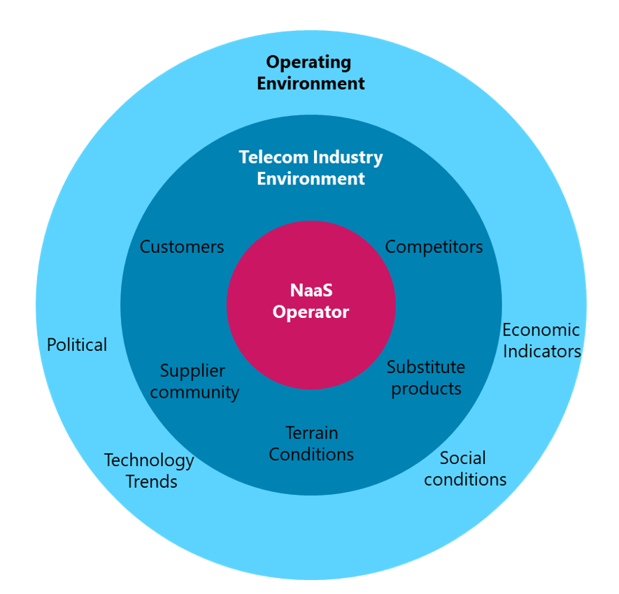
Figure 4. Environment Factors Diagram
More details regarding the specific elements within each category in Figure 4 are provided in the following subsections.
The operating environment, which indirectly affects the NaaS operator comprises Political, Economic, Social and Technological factors. Thus, the operating environment scan is also named as PEST analysis and is part of the Strategy & Scope process. The result of the Operating Environment Scan must be recorded into the Strategy & Scope Definition Template as it will be used on the SWOT Analysis.
Political (includes legal and regulatory)
Includes the political-legal factors comprising the countrys laws and regulations that can influence the NaaS operator objectives and operations.
Economic
The role of economic factors is important in the context of the telecom industry. NaaS operators should account for the national economy, including inflation rates, interest rates, and most importantly, disposable income.
Social
Social factors have a profound influence on the telecommunications industry and its profitability. This is because it has a direct impact on the number and type of services demanded by users.
Technological
The telecommunications industry is highly dependent on technology changes. The NaaS operator should gain most of these technological trends.
3.3 Telecom Industry Environment Scan
As shown in Figure 4, the NaaS operator must be aware of the Telecom Industry Environment. This section provides general guidelines to collect information about customers, competitors, and other market variables to generate insights for strategies definition.
3.3.1 Telecom Conditions Evaluation
Suppliers Environment
A part of the Environmental Analysis is the evaluation of the available suppliers and their effect on the environment. The NaaS operator suppliers environment is mainly composed of the following elements:
The information regarding suppliers environment can be collected by performing a research on the web sites of the different suppliers.
Geographic Conditions
An analysis regarding the terrain conditions must be conducted, especially in rural areas. The specific geographic features (e.g. mountains, dense forest) may significantly complicate the network deployment for remote populations as the access to the site for construction and maintenance may complicate. Furthermore, harsh climates (e.g. extreme hot or cold) can make the operation and maintenance tasks of the site more challenging.
This analysis has a direct impact on the subsequent design and deployment phases as often extensive microwave or fiber optic laying must be required in the transport network. If the terrestrial solutions are not feasible, NaaS operators often have to rely on satellite transport with additional expensive bandwidth fees to connect remote areas.
In addition to the terrain, the climate can also have a significant impact on the satellite signals as these are vulnerable to rain conditions that can occur regularly in tropical areas.
In further deployment phases, it is important to perform a Technical Site Survey (TSS) on each site to clearly define the geographic conditions.
Basic Infrastructure
The network deployment in rural and remote locations is directly impacted by a lack of basic infrastructure (e.g. power grid, road access). If adverse conditions are presented, the Naas operator must build each site in a self-sufficient manner (e.g. solar energy-based). This represents an increment in the deployment costs and subsequent operations and maintenance costs.
Furthermore, the quality of the basic infrastructure must be identified as bad quality infrastructure may represents additional costs on the site operations (e.g. bad quality power grid may require backup batteries).
The Technical Site Survey (TSS) on each site in further deployment phases clearly defines the existing basic infrastructure conditions.
3.3.2 Customer Segmentation and Targeting
The NaaS operator should recognize that all customers have to be approached in different ways as their needs and values are different. Rather than trying to compete in the entire market, the NaaS operator must identify parts of the market that can be served best and most profitably.
The most effective way to achieve this is to segment customers. The goal of creating customer segments is so that specific customers that have similar needs can be targeted with the same products and pricing.
The following questions can help to identify the target Customer Segments:
In the context of NaaS operator environment, the potential customers are:
Once segments are identified, the NaaS operator must determine its particular needs and the most appropriate way to satisfy them by providing value. The following process illustrates the process to perform customer segmentation.
- Segment Name: Establish a name for the target customer segment.
- Evaluate: After the customer segments have been identified, evaluate them based on the following criteria:
- Identify Customer Needs: List the needs or wants of this customer segment. Target customer segments can be grouped based on similar needs, motivation, or behavior.
- Identify Customer Characteristics: List the characteristics that describe this segment. The major categories of characteristics are: demographic, geographic and usage.
- Customer Profile Development: Create a customer profile that uniquely describes this target customer segment.
In the context of NaaS operator environment, some alternatives of customer segment definition are:
3.3.3 Competitive Analysis
The competitive analysis aims to assess the opportunities and threats that may occur from those organizations competing for the same business. The NaaS operator needs to have an understanding of what competitors are or arent offering the same service to potential customers.
Unless explicitly stated, along this document the term customer refers to entities that buy services directly from the NaaS operator (e.g. MNOs, MVNOs). In contrast, end-user term refers to subscribers that use the LTE services. It is important to mention that not all the end-users buy services directly from the NaaS operator, as some of them will buy the service from an MVNO.
In order to identify the organizations that compete for the same customers, the following actions must be performed:
The following subsections examine different types of organizations that compete for the same group of customers as NaaS operators. They can be divided into two main groups: Direct competitors and Substitute Products.
Direct Competitors
In the NaaS operator context, the direct competitors are:
Substitute Products
A substitute product performs the same or a similar function as the NaaS operator offer but by different means. Substitutes offer the greatest threat when they can provide customers with better service at lower costs through changes that improve the value of their products or services.
In the NaaS operator context, the main substitute products can be in the form of:
In order to quantify the specific threat of substitute products, it is essential to look at the price-performance trade-off between the substitute and the NaaS operator services.
3.4 SWOT Analysis
This section presents a Methodology to develop a SWOT (Strengths, Weaknesses, Opportunities, and Threats) Analysis to evaluate the NaaS operators strategic position.
3.4.1 Identify Opportunities and Threats
Opportunities are situations that potentially exist but must be acted on so to benefit the NaaS operator. Most relevant opportunities are those that offer important avenues for profitable growth, those where a company has the most potential for competitive development, and those that match up well with the financial and organizational resource capabilities that the company already possesses or can acquire.
In contrast, Threats refer to external conditions or barriers that may prevent the NaaS operator from reaching its objectives.
The areas presented in Table 1 can help to identify opportunities and threats that can be identified using the results of the Operating and Telecom Industry Environmental Scan.
|
Area |
Potential opportunities and threats |
|
Operating Environment |
– Political/Legal – Environment – Social – Technological |
|
Telecom Industry |
– New competitors – Substitute products – Competitive rivalry |
|
Competitors |
– Identified competitors – Strengths, weaknesses |
Table 1. Areas of potential Opportunities and Threats
3.4.2 Identify Strengths and Weaknesses
Strengths refer to the areas (e.g., operations, management, marketing) in which the NaaS operator performs successfully. An analysis of organization strengths should be market and customer-focused because strengths are only meaningful when they assist in meeting customer needs. Strengths give the organization enhanced competitiveness.
On the other hand, Weaknesses refer to any limitations that the NaaS operator faces in developing or implementing a Strategy. A weakness is something an organization lacks or does poorly in comparison to others, or a condition that puts it at a disadvantage. Weaknesses should also be examined from a customer perspective because customers often perceive weaknesses that an organization cannot see.
The strengths and weaknesses can be discovered via brainstorming process among the elements of the leadership team and by breaking them down in the areas presented in Table 2.
|
Area |
Potential strengths and weaknesses |
|
Capabilities |
– Human – Organizational – Knowledge |
|
Resources |
– Financial – Physical – Intangible |
|
Processes |
– Deployment – Operational – Customer management |
Table 2. Areas of potential Strengths and Weaknesses.
3.4.3 SWOT Development
A SWOT analysis is a methodology to examine an organization by looking at the internal strengths and weaknesses in relation to external opportunities and threats. This analysis takes as an input all the previous analysis (i.e. Operating and Telecom Industry Environmental Scan, Customer Segmentation, Competitive Analysis). By creating a SWOT analysis, all the important factors affecting the organization can be seen together in one place. Its easy to read, easy to communicate, and easy to create.
The following list considers some questions to be asked during the development of the SWOT. These questions should have been already answered in the analysis prior to the SWOT development:
Once the SWOT Analysis is completed, the information should be used to start the development of strategies that will leverage the NaaS operators strengths to pursue opportunities, while also countering identified weaknesses and threats that might undermine its efforts. The SWOT analysis is a crucial input to develop strategic alternatives and potential goals.
Additionally, the Naas operator can use the SWOT Analysis Template to support the SWOT Analysis development.
4 Mission and Scope
The content of this section illustrates the procedures to establish a charter by defining the particular mission, vision and service definition for the NaaS Initiative.
4.1 Mission Statement Development
The mission statement is a declaration of the NaaS operators purpose and spotlights the customer needs that are endeavoring to be met. To build a solid foundation for a successful organization, it is essential to have a written, clear, concise, and consistent mission statement that simply explains the NaaS operators purpose.
The mission statement should serve as a guide for day-to-day operations and as the foundation for future decision-making. The following guidelines should be considered when writing or evaluating the mission statement:
Additionally, the Naas operator can use the Mission Statement Assessment Checklist to assess the above criteria on the developed mission statement.
4.2 Vision Statement Development
The vision statement provides a clear mental picture of what will the NaaS operator look like in 5 to 10 years from now. Forming a strategic vision should provide long-term direction, delineate the organizational activities to be pursued and the capabilities the NaaS operator plans to develop. It serves as a unifying focal point for everyone in the Organization.
An effective vision statement consists of the following elements. The specific vision statement generated by the NaaS operator may nor incorporate all these elements, but they must be considered when casting the statement:
4.3 Identify Competitive Advantages
The competitive advantage is what the NaaS operator does or potentially could do better than similar organizations. One result of a well-developed and executed strategic plan is to develop a unique competitive advantage. A sustainable competitive advantage(s) is the foundation, the cornerstone of the strategy.
The following criteria must be considered to evaluate the Competitive Advantage identification:
Some examples of competitive advantage in the NaaS operator context are:
4.4 Technologies and Services Definition
This section examines different technologies and services that can be included as part of the catalog to be offered to customers.
4.4.1 Radio Technologies
4G Long-Term Evolution (LTE)
4G LTE is a wireless communications standard developed by the 3rd Generation Partnership Project (3GPP) and it is reflective of the coverage consumers now expect. LTE delivers the ability to use end devices to their peak functionality.
The recommendation is that LTE must always be the default technology to be deployed by NaaS operators.
Pre-Existing 3G (UMTS) / 2G (GSM) Network
The rural areas may have coverage with legacy technologies (e.g. 3G UMTS and 2G GSM) provided by some existing MNOs. However, these technologies are not capable of supporting todays user requirements.
It is not recommended to deploy 3G equipment as the use of this technology will be declining in the coming years. However, in case of deployment of 3G equipment, the NaaS operator must ensure that it can be depreciated while still being used.
The recommendation is that 3G and 2G technologies should not be deployed and only be considered for CS Fallback capabilities.
5G Radio Technology
The fifth-generation (5G) of cellular technology increases the speed and responsiveness of wireless networks. Over this network, data can be transmitted at multi-gigabit speeds, with potential peaks of 20Gbps. Moreover, it offers a latency of 1ms that enable real-time applications. 5G will also increase the available bandwidth due to advance antenna technology implementation.
Despite all the advertised capabilities, 5G deployments have not been massively implemented as the technology and equipment standards are still in process of development.
The recommendation is that 5G radio technology should not be deployed in the NaaS operator network until successful tests are successfully completed in NaaS operator laboratories or flagship rural deployments.
4.4.2 Voice Services
The NaaS operator must evaluate if Voice Services will be part of its catalog of services as it represents special considerations in the network architecture. It can select to only provide data services for their customers.
If the NaaS operator wants to offer voice services as part of its catalog service, there are three available options that are described in the following subsections. Further details on the implementation of these alternatives are provided in the Mobile Core Architecture module.
Circuit Switched FallBack (CSFB)
In this scenario, the LTE handset falls back to 3G or 2G to establish a traditional circuit switching connection. As CSFB is not strictly an LTE based voice service, rather EPC assists the device to fall back to a 2G/3G network. It presents many drawbacks such as, higher call-setup-delay or just acceptable quality voice.
However, if the NaaS operator has a pre-existing 2G/3G network then the CSFB functionality must always be deployed for simplicity.
Voice over internet protocol (VoIP) / Over the top (OTT) Application
VoIP is the transmission of voice and multimedia content over Internet Protocol (IP) networks. This service is also referred as Over-the-top (OTT) Application and PoC (Push-to-Talk over Cellular). These type of applications can be free (e.g. WhatsApp, Facebook) or be provided by the VoIP service provider.
VoIP is the recommended alternative when the NaaS operator wants to provide voice services through its 4G-only network and has budget limitations. However, it should be noted that the voice quality will never match VoLTE.
Voice over LTE (VoLTE)
VoLTE is the industry-recognized solution for providing a packet voice service over IP via LTE access technology. When the NaaS operator has the economical/knowledge capabilities and agreements with an IMS network provider, then the option that will deliver HD voice is VoLTE.
Furthermore, NaaS operators should consider the availability of VoLTE-capable devices on its market and the feasibility of VoLTE business case with its customers. Additionally, the customer (e.g. MNO) need to support VoLTE.
5 Strategy Design
The present section describes the definition of the strategy and long-term objectives that ultimately will guide the downstream activities.
5.1 Organization-Wide Strategies Definition
An organization-wide strategy is a general statement(s) that guides and covers a set of activities. It answers the question how. By consistently executing an organization-wide strategy, the NaaS operator can provide a product or service thats better than its competition.
In this step of the planning process, the synthesized information in the SWOT analysis, the mission, vision and competitive advantages are used to develop the organization-wide strategy or strategies that will guide goal and action planning.
The following elements summarize the core of strategy and should be accomplished in the definition of an organization-wide strategy:
There are certain areas within the NaaS operator that require the definition of a strategy that guides the decision of subsequent phases. These areas are presented in Figure 5 and are examined in the following subsections.
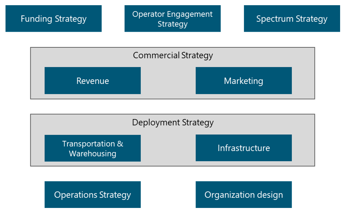
Figure 5. Strategy Map
Additionally, the Naas operator can use the Strategy & Scope Definition Template to support the definition of their own strategies.
5.1.1 Funding Strategy
A primary element to develop a telecommunication network is to identify the funding methods to deploy the network. There are different strategies for funding telecommunication projects that are presented in Figure 6. NaaS operators must evaluate which of them will be used to fund the initiative. The final decision must consider, among other elements, the applicable political and regulatory conditions and it must be recorded in the Strategy & Scope Definition Template.
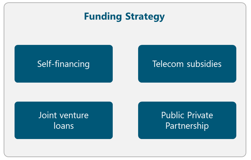
Figure 6. Funding Strategy Alternatives
In the following subsections, multiple alternatives that can be used in different countries around the world are presented.
Self-financing
Most of the time, self-financing method is only applicable when the NaaS operator already has an existing network in the country. In this way, the costs of infrastructure can be reduced as existing towers and fiber can be used to support the deployment of the 4G network. Furthermore, the profits from the existing network can be used to build out the new network deployment.
In case that the cost of deployment exceeds the NaaS operators financial capabilities, an alternative method must be evaluated.
Telecom subsidies
An alternative option is to apply for telecom subsidies in the region. A definition of a subsidy is a grant or a monetary gift, usually given from the government to a specific project. Another form of subsidies is that the government reduces the taxes for a company that needs assistance; thereby they get more financial resources.
Joint venture loans
Joint venture loans are an option when the loan for the investment cannot be covered for one single company. This means that two or more companies share the risks and benefits of the loan.
Joint ventures can result in an effective partnership, but to make this happen, they must be structured. To ensure this, it is recommended that an independent president is chosen.
A joint venture often ends when the predetermined goal has been reached (e.g. the deployment completion) so all involved parties need to be prepared for that.
Public-Private Partnership
This partnership means that the private and public sectors share the risk for the project. If there is any risk that they together cannot control, the public sector usually takes responsibility for that risk.
Principally a public-private partnership is a form of privatization, but with a big difference that the public sector is also involved. The partnership is involving the government and one or more private sector companies.
5.1.2 Operator Engagement Strategy
The traditional approach of network deployment, where each operator builds its own network infrastructure is not efficient in rural markets with low population density. In turn, the NaaS operator must analyze ways to co-operate with other operators on expanding network coverage whilst preserving healthy competition in service provision. In this way, an MNO can become a partner for the NaaS operator.
The Operator Engagement has multiple dimensions in the sense that include elements of the Spectrum, Commercial and Infrastructure Strategies. These elements are examined in its corresponding section, but the final definitions must be consolidated in an Operator Engagement Package in order to present them to the operators.
Figure 7 illustrates different alternatives to perform the Operator Engagement. The NaaS operator must evaluate them and select the most appropriate according to its conditions. The final decision must be recorded in the Strategy & Scope Definition Template.

Figure 7. Operator Engagement Strategy Alternatives
The following subsections describe the way to engage different types of operators as well as their impact on the NaaS operator strategy. It must be noted that the decision of the operators to be considered to interconnect with, has a direct impact on the RAN and Mobile Core implementation.
5.1.2.1 Mobile Network Operators (MNO)
The primary driver that an existing Mobile Network Operator can consider to set an agreement with the NaaS operator is to extend its coverage to rural scenarios. For this, the scenarios in the following subsections can be implemented.
The impact on the NaaS operators Radio Access Network and Mobile Core implementation are further detailed in the respective Architecture Modules.
Network Roaming Agreements
In this scenario, NaaS Operator owns the RAN and the core network and redirects the traffic to MNOs core networks. Additionally, the user might have to enable roaming on their phone to access the NaaS network.
This scenario for the NaaS operator implies that a complete RAN and transport infrastructure must be deployed using its own spectrum. Additionally, the Mobile Core must also be implemented along with the interconnection to MNOs Mobile Core.
RAN Sharing Agreements
NaaS Operator can provide its RAN infrastructure to multiple MNOs based on different RAN Sharing schemes (e.g. Multi-Operator RAN, Multi-Operator Core Network). In this scenario, a pool of radio spectrum is formed using the available sources (e.g. NaaS operator, MNO). In addition, MNOs rely on the NaaS radio/transport infrastructure to provide service to the end user.
This scenario for the NaaS operator implies that a complete RAN and transport infrastructure must be deployed and its radio spectrum (if existing) can be used to conform the pool of spectrum.
5.1.2.2 Mobile Virtual Network Operator (MVNO)
A Mobile Virtual Network Operator (MVNO) is a virtual operator that offers mobile services under its trademark by using network services from a third-party mobile operator. The MVNOs can be further classified in different categories according to their characteristics.
The impact on the NaaS operators Mobile Core implementation are further detailed in the Architecture Module.
Full-MVNO
In this scenario, the NaaS operator just provides the access network infrastructure and, sometimes, part of the core network. Therefore, the MVNO must build and maintain its own Mobile Core. As a result, the MVNO manages its own customer base and associated services independently from the host operator.
This scenario for the NaaS operator implies that a complete RAN and transport infrastructure must be deployed. In addition, the NaaS operator must possess granted radio spectrum. Finally, the interconnection to MNOs Mobile Core needs to be implemented.
Light-MVNO or Re-seller
The MVNO just provides its brand and its distribution channels. In contrast, the NaaS operator provides the access and transport, as well as the mobile service. This is the model that requires the lowest investment from the MVNO, therefore the fastest to implement.
A Light-MVNO delegates the networks operational management to its host operator, in order to focus on customer relations.
This scenario for the NaaS operator implies that a complete RAN and transport infrastructure must be deployed. . In addition, the NaaS operator must possess granted radio spectrum. Finally, a complete Mobile Core must also be implemented.
5.1.3 Spectrum Strategy
Efficient spectrum management has an important impact on the quality and reach of affordable mobile services. Figure 8 displays the different alternatives to obtain and manage the radio spectrum.The NaaS operator must evaluate each alternative and select the most appropriate according to its conditions. The final decision must be recorded in the Strategy & Scope Definition Template.
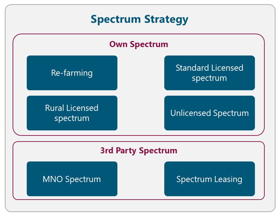
Figure 8. Spectrum Strategy Alternatives
The following subsections examine different approaches to obtain and manage the radio spectrum.
It should be noted that a spectrum license should also be considered for transport microwave equipment. However, microwave spectrum considerations are deeply analyzed in the Transport & IP Architecture module.
5.1.3.1 Own Spectrum
The first alternative is that the NaaS operator manages and operates its own granted spectrum. The following subsections examine different alternatives to achieve this.
Re-farming
If the NaaS operator has an existing operating mobile network, it can use the already licensed spectrum to deploy LTE services. Existing low-frequency spectrum (e.g. 900MHz) used for 2G/3G services can be more effectively reused for 4G service deployment.
Spectrum re-farming is a cost-effective way to increase capacity in existing networks without the need to bid for new spectrum and by reutilizing infrastructure to overlay LTE.
Standard Licensed spectrum
The NaaS operator can follow the standard licensed mechanisms to acquire sufficient spectrum to provide broadband mobile services.
However, the cost of the spectrum fee may impact the overall business case. Additionally, the process of acquiring spectrum is highly time-consuming given its complexity.
Rural Licensed spectrum
Spectrum regulators have been encouraged to clear the 700 MHz and 800 MHz spectrum through the migration to digital television, which can release the so-called digital dividend spectrum for use by mobile services, especially in rural areas.
Furthermore, in some countries, the local government provides specific telecom subsidies and grants to these types of radio bands in order to promote the coverage expansion in rural areas. The NaaS operator can analyze its applicability to these special programs.
Unlicensed Spectrum
The utilization of unlicensed spectrum in the 5GHz range allows an operator to deploy LTE services without the necessity of a license for spectrum. However, the use of unlicensed spectrum imposes transmission power limitations, which limits the coverage area.
In addition, the NaaS Operator needs to verify if other operations are using unlicensed spectrum in the area, as this may cause a considerable amount of interference.
The NaaS Operator must be aware that the operation of LTE in unlicensed spectrum may not be supported by all user devices.
5.1.3.2 3rd Party Spectrum
NaaS operators can use a 3rd party spectrum assigned to provide LTE services. The following subsections examine different options to accomplish this.
MNO Spectrum
NaaS Operators can use the MNO granted spectrum to provide LTE services via different RAN Sharing schemes (e.g. Multi-Operator RAN, Multi-Operator Core Network). In this scenario, the spectrum of the MNO is used and, in some cases, shared.
This scenario imposes some special considerations on the overall network architecture that need to be taken into account and are further explored in the Transport and IP Architecture Module.
Spectrum Leasing
NaaS operators can lease the spectrum from a third party (e.g. MNO, WISP) in order to provide LTE services. This represents an additional recurrent cost to NaaS operators that may impact the overall deployment business case.
In addition, an accurate capacity forecast analysis must be performed in order to determine the amount of bandwidth to lease. If this is not well-forecasted, the NaaS operator may over or underutilize the leased bandwidth.
5.1.4 Commercial Strategy
The commercial strategy of the NaaS operator is composed of two elements: Revenue Strategy and Marketing Strategy. Figure 9 displays the different alternatives related to the Commercial Strategy. The NaaS operator must evaluate each alternative and select the most appropriate according to its conditions. The final decision must be recorded in the Strategy & Scope Definition Template.
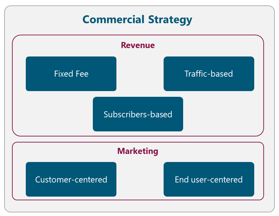
Figure 9. Commercial Strategy Alternatives
5.1.4.1 Revenue
The Revenue Strategy must identify Revenue Streams within the NaaS operator environment. The nature of each of the streams is different, so a specific Pricing Strategies are required for each of them.
The applicable pricing strategies in the context of the NaaS operator are:
In this way, the different Revenue Streams can be classified accordingly. Table 3 displays a typical Revenue Streams classification for a NaaS Operator.
|
Revenue Stream |
Description |
Customer |
Pricing Strategy |
|
LTE Service Provisioning |
Revenue is generated by the provision of the LTE service to 3rd party entities. |
MVNO, specially Light-MVNOs |
– Fixed Fee – Traffic-based – Subscribers-based |
|
RAN Infrastructure Leasing |
Revenue generated by leasing its RAN infrastructure |
MNOs or WISPs |
– Fixed Fee |
|
Roaming Agreements |
Revenue generated for providing LTE service to MNO’s subscribers in an area where only the NaaS operator have coverage |
MNOs |
– Traffic-based |
Table 3. Typical Revenue Classification for a NaaS Operator.
5.1.4.2 Marketing
The Marketing Strategy describes the specific types of Marketing Models that NaaS operators will implement in order to promote its services among its direct customers and end-users.
The marketing models that the NaaS operator should consider are presented in the following subsections.
Customer-centered
This model is part of the Engagement Operator package and is focused on promoting the differentiators of the NaaS operator services among its direct customers (e.g. MNOs, MVNOs). The aim is to demonstrate and explain the advantages of using NaaS operator services (e.g offer cheaper broadband mobile service focused on rural connectivity).
Once an engagement is established, periodic approaches can be performed in order to consolidate and strengthen NaaS operator position.
The usual channels of communication used by this model are Email and Face-to-face Meetings.
End-user-centered
The focus of this model is to announce and promote the NaaS operators services among end users (i.e. mobile subscribers). These end users may not buy directly from the NaaS operator, however, they need to be aware that they are making use of its services. This type of marketing is very important when a NaaS operator brings connectivity to a new area, so the inhabitants aware that this new connectivity exists.
This model expects to encourage further positive purchase-related behavior. This can be in the form of subscribers visiting the NaaS operator website, read about it, and share.
The typical channel communication used by this model is mass media (e.g. Social media, TV spots, radio advertisement, printed newsletter)
5.1.5 Deployment Strategy
The commercial strategy of the NaaS operator comprises two aspects: the Logistics & Warehousing and the Infrastructure strategy. Figure 10 displays the different alternatives related to the Logistics & Warehousing Strategy. The NaaS operator must evaluate each alternative and select the most appropriate according to its conditions. The final decision must be recorded in the Strategy & Scope Definition Template.
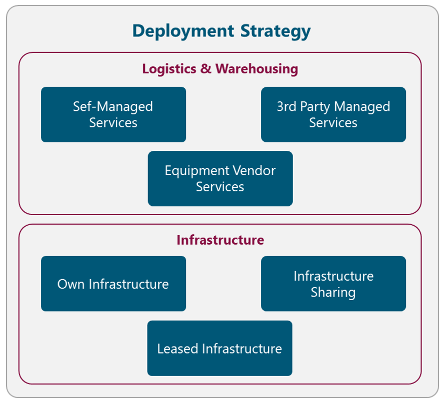
Figure 10. Deployment Strategy Alternatives
5.1.5.1 Logistics & Warehousing
Logistic & Warehousing describes the form in which all the network equipment and ancillaries are stored and distributed. The possible alternatives to implement these services are described in the following subsections.
Self-Managed Services
One alternative to perform the Logistics and Warehousing services is that the NaaS operator implements them with its own resources and facilities. This option is only applicable if the NaaS operator already has an existing implementation of these services or if it possesses enough resources to implement them. Another case that fits this strategy is for small NaaS Operators with no more than a handful of sites as little space to store equipment is required.
The implementation of this option requires an additional design phase if the Logistics & Warehousing services are not already deployed. Furthermore, it may represent additional costs such as Warehouse rent of space and specialized Management Systems.
More details on the processes related to Logistics & Warehousing design and implementation are included as part of the Logistics & Warehousing Module.
3rd Party Managed Services
Another option for the NaaS operator consists of hiring a 3rd party Logistics and Warehousing Company to manage these services. In this way, the operations of these services are the responsibility of the 3rd party, lightening the operational workload of the NaaS operator.
This option is recommended for the NaaS operator as the burden of these services will decrease when the deployment phase is completed and only will apply for the spare equipment.
Equipment Vendor Services
Some vendors offer Transportation & Logistics services for their equipment, so NaaS operators can rely on them. However, this only applies to certain regions and vendors that include these services as part of its purchase agreements. If the vendor provides these services as an additional feature, the considerations of the 3rd Party Managed Services are applicable.
5.1.5.2 Infrastructure
The Infrastructure strategy describes the model that NaaS operators will implement to build and manage the required network infrastructure (e.g. Fiber Infrastructure, Sites, and Towers). The following subsections examine different models to implement this strategy.
Own Infrastructure
The NaaS operator can perform these activities with its own resources if it already has an existing infrastructure (e.g. MNO with existing mobile network, Tower/Fiber Companies) or if it possesses enough resources (e.g funding and personnel) to deploy them.
The development of this option requires an additional design phase for the new infrastructure to be deployed and additional time to acquire the sites. Moreover, it may represent high additional costs such as material (e.g. fiber optic, steel), machinery and equipment construction.
More details on the processes related to the infrastructure design and implementation are included as part of the Tower/Site construction and Fiber Construction modules.
Infrastructure Sharing
Infrastructure sharing models can have a profound, positive impact on the economics of network deployment into rural and remote areas. In this model, the involved partners share the capital and investment costs of the network infrastructure deployment. For NaaS operators, potential partners to be considered by the NaaS operator are MNOs with no coverage in the area, Tower or Fiber companies.
When the infrastructure is already deployed, the operation and maintenance tasks can be shared or can be absorbed by one of the parties as part of the initial agreements.
Leased Infrastructure
If there is infrastructure available in the area, the NaaS operator can lease the infrastructure to a 3rd party (e.g. MNO with 2G/3G coverage, Tower/Fiber Companies). In this form, the NaaS operator can avoid investment in new infrastructure deployment. The most common type of leased infra is in the form of telecom towers and transport networks.
Additionally, the operation and maintenance of the infrastructure are absorbed by the 3rd party, lightening the operational workload of the NaaS operator.
5.1.6 Operations Strategy
The operations strategy defines the model that NaaS operators will follow to perform the network operation and maintenance tasks. This includes the management of the Network Operation Center (NOC), Field Maintenance and Service Operations Center (SOC), as required. Figure 11 displays the different alternatives related to the Operations Strategy. The NaaS operator must evaluate each alternative and select the most appropriate according to its conditions. The final decision must be recorded in the Strategy & Scope Definition Template.
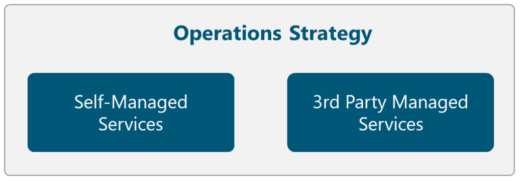
Figure 11. Operations Strategy Alternatives
Self-Managed Services
The NaaS operator can perform the network operation and maintenance activities with its own resources and facilities.
However, it represents additional costs for the required specialized staff to perform the activities. Furthermore, it may represent additional costs such as rent of space and specialized Network Systems.
3rd Party Managed Services
An alternative option is to hire a 3rd party Company that manages the network operation and maintenance activities. In this way, these activities are the responsibility of the 3rd party, lightening the operational workload of the NaaS operator.
This model is also convenient when sites are deployed in rural locations that are far away the locations the NaaS operates from. Therefore, the disposal of local resources is also a deciding factor to select a 3rd party company.
In this scenario, the cost of specialized hardware cannot be avoided because most of the network equipment requires a Licensed Software to perform the network operation and maintenance activities.
5.1.7 Organization Design
The organization design specifies the division of functional areas within the NaaS operator structure. It establishes the different levels of hierarchy within the organization and delimits the responsibilities of each of them.
Figure 12 presents a typical NaaS operator organizational structure. This structure includes a Leadership Team which develops the Strategy & Scope and the High-level Project Plan.
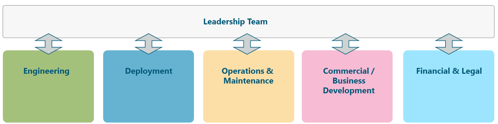
Figure 12. Typical NaaS operator Organizational Structure.
displays five areas that are required for the successful operations of the NaaS operator:
Depending on the size of the NaaS operator, the management and supervision of the available resources can be done by one person for all the areas. However, in larger organizations, a manager for each function might be required. The specific resource requirements for each of the presented areas are examined in more detail in the High Level Project Plan Module.
5.2 Long-Term Strategic Objectives Definition
A long-term strategic objective is a long-term (e.g. 3-5 years), broad, continuous statements that holistically address the different areas of the NaaS operator. Long-term objectives that are viable and appropriate should remain as something that will not change and must be achieved.
The long-term strategic objectives should consider the SWOT analysis. In this way, they will be built on the strengths of the company, fix weaknesses, pursue opportunities and resolve any threats.
In order to define the long-term strategic objectives, the key activities that need to be performed to achieve the vision must be identified considering the strategies presented in section 5.1.
An example of a long-term strategic objective in the NaaS operator context is:
5.3 Set Organization-Wide Goals and Measures
Once the long-term objectives have been identified, they must be translated into goals and measures that can be clearly communicated to the leadership team. Effective goals clearly state what, when, how, and who, and they are specifically measurable. They should address the tasks that need to be performed in the short-term (1-3 years) to achieve the strategic objectives.
The organization-wide goals should present the following characteristics:
Examples of long-term strategic objectives in the NaaS operator context that comply with the SMART characteristics are:
6 Organizational Governance & Performance
This section includes methodologies to control and manage the implementation of the defined strategies. The governance definitions aim to communicate the overall strategies as well as measure and monitor progress towards strategic targets.
6.1 KPI Definition
Key Performance Indicators (KPIs) are the critical indicators of progress towards an intended result. KPIs provide a focus for strategic improvement and create an analytical basis for decision making.
In order to generate a KPI for the strategy implementation, the following elements must be defined:
A useful form to present the KPIs is through the use of the Strategy Scorecard as displayed in Table 4. The NaaS operator should construct a similar Strategy Scorecard with the specific objectives KPIs for each of the Strategies presented in Section 5.1.
|
Strategy Name |
||||
|
Goal |
Units of Measure |
Target |
Frequency |
Source |
|
Goal 1 |
|
|
|
|
|
Goal 2 |
|
|
|
|
Table 4. Strategy Scorecard Format
The aim of the Strategy Scorecard is to identify adjustments over the time according to the KPIs behavior.
An example of the definition of a KPI in the NaaS operator context is presented in Table 5. KPI Example.
|
Deployment Strategy |
||||
|
Goal |
Units of Measure |
Target |
Frequency |
Source |
|
Operational Sites |
Number of sites |
9 sites |
Monthly |
Project Plan |
|
Subscribers |
Number of subscribers |
3300 subscribers |
Annually |
Project Plan |
|
Data Volume |
Aggregated Mbps |
600 Mbps |
Monthly |
Project Plan |
Table 5. KPIs Example
6.2 Establish Schedule for Progress Reviews
Holding regular strategy reviews is the key to the implementation of the Strategies. These meetings will give the ability to manage activities that drive future results and hold people accountable for making sure those activities happen. Furthermore, the adopted strategies can change based on competitors and government actions, therefore, strategy meetings are important as the world around the NaaS evolves.
A Schedule for Progress Reviews must be defined, describing the specific dates and communication channels to communicate with stakeholders regarding the strategic plan and the associated progress. This schedule should be employed by strategy managers in the organization to ensure the awareness about the intent and progress of the strategic plan is fully understood by key stakeholders.
The following steps must be perform to define the Schedule for Progress Reviews:
6.3 Goal Tracking Methodologies
The NaaS operator must establish the performance management review system in order to track the progress towards the goals to identify possible issues and make course corrections if necessary.
One alternative is to use the Strategy Scorecard method presented in Section 6.1 as a performance management review system. In this way, the Strategy Scorecard must be presented by the responsible people during each meeting.
Additional tools such as management and technology systems can help track the progress of the plan and make it faster to adapt to changes. As part of the system, milestones can be built into the plan that must be achieved within a specific time frame.
6.4 Review and Adapt Process
A Strategic Planning Retreat must be held at least once per year. During this session, all the elements in the Strategy, including the Mission and Vision Statements must be reviewed in order to confirm that are current and still relevant to the NaaS operator.
The following elements must be considered to perform the Strategic Planning Retreat:
After updating the Strategy Plan, it must be distributed to all elements within the organization to align the priorities and ensure that everyone knows what they are responsible for.
1. Introduction: High Level Overview
Development of the High-Level Project Plan is the immediate next step after Strategy & Scope definition of the NaaS Initiative. Together with the NaaS Strategy, the High-Level Project Plan serves as a roadmap to stand-up the NaaS Operator. It provides the reference plan to manage and control critical tasks. It also provides task and timeline guidance for detailed planning associated with Design, Deployment and Operation of the Network.
This module describes the key planning areas and components. It aims to transform the Strategic Plan into an actionable plan in the key areas of Schedule, Resources and Communication Plans.
Together, these elements comprise the High-Level Project Plan, which is the catalyst for action and provides the NaaS Operator and key stakeholders a holistic view of what needs to be done, the resources required, and a guidance on how to communicate the plan across the NaaS Organization.
1.1 Module Objectives
This module will enable NaaS Operators to establish a High-Level Project Plan to organize and coordinate all the activities required to build and turn-up a NaaS Initiative. The specific objectives of this module are to
- Provide an information base of fundamental planning aspects for a NaaS Initiative, creating awareness of the interactions among these aspects and NaaS Strategy.
- Guide the NaaS Operator to identify all the required resources and generate an efficient plan for resource acquisition and utilization.
- Provide guidelines to identify key tasks and milestones, and generate a High-Level Schedule that aims to achieve NaaS Operators strategic goals and objectives.
- Support NaaS Operators to define a Communications Plan that provides an Organization-wide structure for meetings, reporting, communication channels and documentation.
1.2 Module Framework
The Module Framework in Figure 1 describes the structure, interactions and dependencies among different NaaS operator areas.
Strategic Plan & Scope is the first stream to build the NaaS Operator. The modules in this stream aim to drive strategic decisions that impact all the downstream modules. From this point, High-Level Network Architecture can be defined, establishing the guidelines for Network Design which in turn kick-starts the deployment phase.
High-Level Project Plan comes after Strategy & Scope definition. However, there is an interaction between the outputs of these modules, in the sense that High-Level Project Plan may trigger updates to Strategy & Scope.
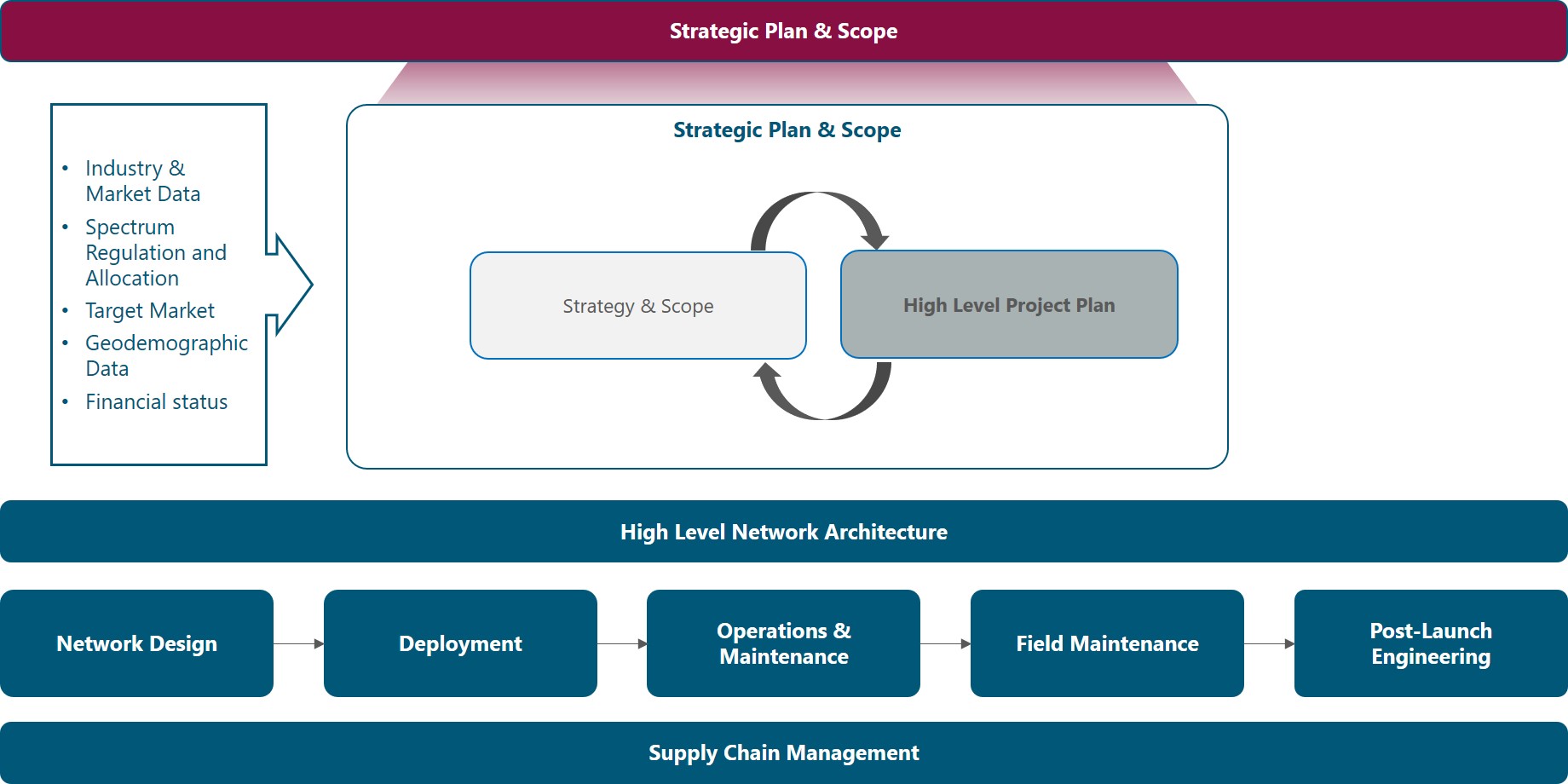
Figure 1. Module Framework
Figure 2 presents the High-Level Project Plan functional view, where the main functional components are exhibited. Each component is discussed in its own section of the outline, detailing the impact on other blocks and a process to generate an integrated High-Level Project Plan.
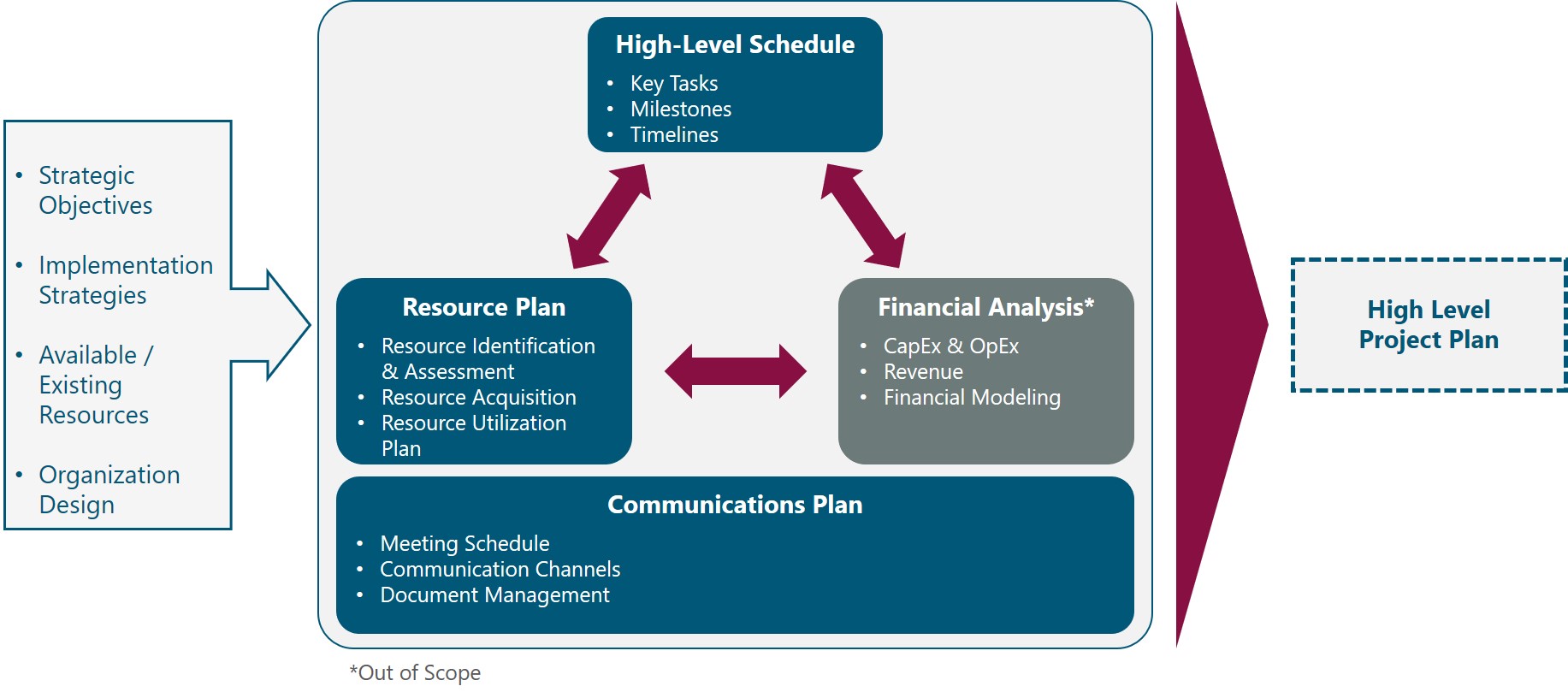
Figure 2. High-Level Project Plan Functional View
The rest of this module is structured as follows: Section 2 presents an overview of the NaaS Planning components and its interaction with the Strategy. Sections 3 to 5 provide deeper analysis and guidance to perform actual Resource, Schedule, and Communications Plan in the context of rural NaaS initiatives.
2 High-Level Project Plan Overview
This section presents the key aspects and components to elaborate a High-Level Project Plan, emphasizing their relevance for the NaaS Operator and interdependency with the NaaS Operator Strategy & Scope.
2.1 Strategy & High-Level Project Plan Interaction
Strategy and scope of the NaaS Operator are first established to set the route that the NaaS Initiative will take and the general methods to be used to reach the long-term objectives.
However, the only way the Strategy gets executed is to align resources and actions through an effective Project Plan that translates the Organization Strategies and Objectives into structured tasks and timelines that fit available resources.
Outputs from Strategic Planning are Organization Strategies and Long-Term Strategic Objectives (See Strategy & Scope Module). These outputs are the starting point and provide a general guide for the High-Level Project Plan, which aims to answer how the Strategy and Objectives will be achieved and who must do what to accomplish them.
Based on the above, it is fair to say that the Strategy drives the Project Plan. However, in todays rapidly changing environment, NaaS Operators may find during the development of the Project Plan that certain assumptions are not valid or that additional constraints that werent considered during Strategy definition must be incorporated. Thus, an iterative planning approach must be applied in which findings from the High-Level Project Plan triggers updates to the Strategy restarting the planning cycle until the NaaS Operator approves both Strategy and Project Plan.
This module enables NaaS Operators to establish a High-Level Project Plan to organize and coordinate all the activities required to build and turn-up a NaaS Initiative based on the NaaS Operator strategy.
2.2 NaaS Planning Fundamentals
In the following sections, an initial description of planning components is provided to build a holistic view of the planning process.
2.2.1 Resource Plan Overview
NaaS Operators require different types of resources to plan, deploy and operate the network and the services it provides. These resources can be categorized as follows:
In addition to the resources above, services are considered as part of the Resource Plan. However, it is important to note that services are not the same as resources. Services are provided by 3rd Parties and are used to satisfy a requirement over a period of time, i.e. they are temporary. In some cases, instead of acquiring a specific resource NaaS Operators may decide to contract a service that replaces the required resource.
The Resource Plan specifies how the above resources should be categorized, acquired, managed, and released. The Resource Plan for NaaS Operators must include at minimum the following items:
- Resource Identification. Identification and quantification of the required resources to accomplish objectives.
- Resource Acquisition. Plan and guidelines on how the resources will be acquired. A separate section should be considered for staffing in which specific positions and responsibilities should be taken into account.
- Resource Management. Details on how and when resources will be utilized, considering guidelines for allocation, control, and release of resources.
Further details and guidance for the development of the Resource Plan are provided in Section 3.
2.2.2 Schedule Overview
Project scheduling provides a plan that describes when the Project Milestones will be delivered and the activities involved to achieve these milestones, including duration and dependencies among activities. As part of the High-Level Project Plan, the Schedule serves as a tool for communication, managing stakeholders expectations, and as a basis for reporting.
As can be expected, there is a myriad of tasks that must be planned and managed throughout the Lifecycle of the NaaS Initiative. This Module contemplates activities from NaaS Initiative launch up to the completion of Deployment and entrance into Operations Phase. At a high level, the milestones and tasks can be grouped into three categories:
Specifying the Project Schedule is of paramount importance to manage the timely completion of the Project and the achievement of the NaaS Initiatives goals and objectives. Through the analysis of activities sequences, durations, resource requirements, and schedule constraints the project schedule creates a baseline for project execution, monitoring and controlling.
Conditions of every NaaS Operator are different; thus, specific tasks will vary across the NaaS spectrum based on Operators Strategy, existing resources, size of the network, financial constraints, and technology requirements. In a similar vein, task sequencing, interdependencies and duration may vary as well.
A comprehensive assessment of these variations and a method to develop a Project Schedule is presented in Section 4 through the analysis of a generic schedule. In addition, instruction for customization of the generic schedule is provided, including task duration estimation, task sequencing and schedule validation.
2.2.3 Financial Analysis Overview
A critical component of the High-Level Project Plan is a Financial Analysis or Business Model that models the financial performance of the Initiative. It is the primary tool to get investors to buy-in the Project and obtain private or public funding. Ultimately the Financial Analysis will be the baseline for comparison and the decision instrument to approve the Project Plan.
Based on NaaS Strategy and Objectives, and other components of the Project Plan, the financial analysis presents forecasts for costs, revenues, profits and cash flows, and obtains financial metrics such as return-on-investment (ROI), Break-even Year, net present value (NPV) and internal rate of return (IRR).
This analysis is usually done during the early phases of the NaaS Initiative, sometimes before the Strategy definition, and refined during the Project Plan. Furthermore, each Organization may have a different method, scope, requirements and set of metrics for the Financial Analysis. In consequence, a detailed treatment of the Financial Analysis is out of the scope of the PlayBook and it is left to the NaaS Operator to use the methodology and metrics that best fit their needs and requirements.
In any case, it is important to consider at least the following inputs for the Financial Analysis:
2.2.4 Communications Plan Overview
The Communications Plan is the component of the High-Level Project Plan that documents how communications across the NaaS Organization are structured, implemented and monitored. It defines the mechanisms for communications activities based on information needs, the methods to distribute information and coordinate tasks, and the methods for storage and retrieval of information.
The implementation of an effective Communications Plan provides the following benefits:
For NaaS Operators, these benefits can be translated into one key success factor: it avoids delays and re-work due to miscommunication and lack of coordination. This is of utmost importance to keep the initiative alive and financially healthy due to the high cost of re-work and financial constraints that are faced by rural NaaS Operators.
The Communications Plan for NaaS Operators must include at minimum the following items:
In addition, communication to external entities should be considered, establishing rules and policies to share marketing, technical and other confidential information. External communication should consider any constraints derived from specific legislation or regulation and it is considered out of the scope of this module.
Section 5 presents a detailed view of the Communications Plan providing guidance for the NaaS Operator to build their own Communications Plan.
3 Resource Plan
This section explores the tasks and factors involved in Resource Planning, including guidelines for the NaaS Operator to develop their own Resource Plan.
3.1 Resource Identification & Assessment
The first step towards a Resource Plan is to identify the required resources according to the Scope and Strategy of the NaaS Initiative. This is usually done through brainstorming and resource breakdown techniques using objectives and categories of resources to go from general categories to specific individual resources.
Then, after identifying individual items, each item should be quantified based on the scope and strategic objectives.
To simplify this process, a generic list with the most common resources categories and subcategories, and guidance to identify applicability for the initiative is provided in Table 1. NaaS Operators are encouraged to use this table to identify their required resources.
|
Category |
Subcategory |
Description |
Applicability Criteria |
|
Spectrum |
RAN |
Spectrum used by the LTE System. It could be licensed or unlicensed. |
Always required |
|
Microwave |
Spectrum used by microwave links. It could be licensed or unlicensed |
For NaaS Operators using Microwave backhaul |
|
|
Telecom Infrastructure |
RAN Sites |
Physical Site and civil infrastructure for RAN equipment deployment. Examples are Towers, Poles, Rooftops. Land plots may be considered as well for Greenfield sites This category includes cabling and supporting infra to route cables and host equipment such as cabinets, racks, ODFs and trays. |
Always required. (Type of site and specific requirements vary by NaaS Operator) |
|
Transport Nodes |
Aggregation Sites with existing transport/fiber connectivity that may as well be considered for RAN Installation |
Required except for the case of a network using satellite backhaul only with a 3rd Party or Cloud Mobile Core |
|
|
Datacenters |
IT or Telco Facility that hosts Compute, Networking and Storage Infrastructure that supports Systems and virtualized elements such as virtual EPC |
Required for private cloud implementation to support a virtualized core and other Systems. Does not apply for public cloud services or basic server deployment at an IT room in the Headquarters or other network sites |
|
|
Fiber Infra |
Civil and Optical outside plant infrastructure used to provide transport connectivity. Includes Ducts, Poles, Fiber Cables, Splicing Boxes, etc. |
Required if fiber backhaul is being deployed and/or managed by the NaaS Operator. If using a 3rd Party fiber backhaul service, the NaaS Operator is not responsible for this resource |
|
|
Power Infra |
Power cabling, electrical boards, switches, regulators and grounding |
Always required. Might be included as part of the tower/site leasing service |
|
|
Network Equipment |
RAN |
LTE Base Stations |
Always required |
|
Transport |
Last Mile and Aggregation Transport Equipment consisting of microwave radios, routers, switches, and satellite modems (VSAT) |
Always required. Equipment varies depending on the transport technology |
|
|
Power Equipment & Batteries |
Components of the systems to power equipment at network sites, including solar panels, controllers, rectifiers, power over Ethernet (PoE) injectors, Batteries, etc. |
Always required |
|
|
Antennas |
Various type of antennas required to transmit and receive radio signals. Includes RAN, microwave and GPS antennas |
Always required (at least RAN Antennas) |
|
|
Mobile Core |
EPC and Policy and Charging Control nodes, that are usually implemented as virtualized appliances |
Depends on Strategy and Mobile Core Architecture. Only applies when implementing a mobile core instead of using a 3rd Party or cloud core |
|
|
IT infrastructure |
Servers and networking components that support systems, which might include virtualized network functions |
Required if implementing virtualized elements (e.g. core) or systems in a private cloud environment |
|
|
Installation & Construction Materials |
Cables & Connectors |
Cables, connectors and associated materials (e.g. tape) that are used for equipment installation and connection: Electrical, Coaxial (RF) and Optical Cables |
Always required. Might be provided as part of a 3rd Party Installation & Commissioning service |
|
Mounting Hardware |
Miscellaneous elements required to install and mount network equipment |
Always required |
|
|
Construction Materials |
Structural and building materials required for site and fiber construction, including bricks, concrete, blocks, steel, ducts, pipes, etc. |
Required for site and fiber construction. Usually provided as part of the service with a Construction Company |
|
|
Tools |
I&C Tools |
Tools used throughout the installation and commissioning process, up to acceptance testing such as Smart Phones (UEs) & Test Applications, Power & Hand Tools, RF & Network Testing Tools, Safety Equipment, Communications Equipment |
Always required. Usually provided as part of a 3rd Party Installation & Commissioning service |
|
Construction Tools & Machines |
Heavy Equipment and other construction tools required for site and fiber construction |
Required for site and fiber construction. Usually provided as part of the service with a Construction Company |
|
|
Vehicles |
Cars and trucks for equipment transportation, site surveys, maintenance and any other field task |
Required if the NaaS Operator is expecting to perform site activities through its own personnel |
|
|
Systems |
Network Operations |
Management, Monitoring, Inventory, Ticketing, Billing |
Always Required |
|
Engineering Tools |
RF and Microwave Planning Tools for High and Low Level Network Designs |
Depends on network size and overall strategy. |
|
|
Business/ Enterprise Systems |
Billing and Administrative Software, Document Management, Project Management, etc. |
Systems to be implemented vary by NaaS Operator |
|
|
Facilities |
Buildings |
Facilities apart from network nodes such as Headquarters, Warehousing, and network operation center (NOC) |
Headquarters are always required. Other facilities can be avoided by using 3rd Party Services or converged at Headquarters |
|
Office Equipment & Furniture |
Required items at the office: Desks, chairs, PCs, Printers, Phone, etc. |
Always required. Specific items will depend on NaaS Organization size, structure, and scope |
|
|
Staffing |
Executive Team |
Directors and/or managers responsible for the overall management (Managing Director) and specific departments such as Technical, Operations and Commercial |
Always required. Size and specific functions may vary |
|
Engineering Team |
Personnel in charge of network planning and engineering |
Always required. Size and scope may vary |
|
|
Deployment Team |
Personnel in charge of coordinating and executing site deployment, installation, commissioning and integration |
Always required. Size and scope may vary |
|
|
Operations Team |
Personnel in charge of network monitoring, maintenance, fault management and ensuring service availability and performance |
Size and scope may vary and sometimes can be merged with Deployment Team. |
|
|
Commercial / Sales |
Personnel in charge of engaging with customer MNOs and other business relationships |
Not always required, depending on size and Organization Strategy: Functions may be converged with Financial/Legal |
|
|
Financial / Legal |
Personnel in charge of procurement and legal aspects in the Organization |
Not always required, depending on size and Organization Strategy: Functions may be converged with Commercial/Sales. Legal functions might be outsourced |
|
|
Others (HR, Compliance, etc.) |
Personnel in charge of other supporting and ancillary functions such as human resources, performance, compliance |
Depends on Organization Strategy |
|
|
Services |
Transport & Internet Connectivity |
Enterprise and network connectivity services acquired from a 3rd Party. This includes Terrestrial and Satellite backhaul as well as Internet Connectivity |
Always required |
|
Deployment |
Equipment transportation, Installation and commissioning services for site deployment |
Depends on Organization Strategy |
|
|
Construction |
Civil works to build or adapt a network site or to deploy fiber outside plant infrastructure |
Depends on Organization Expertise and Scope |
|
|
Grid Power |
Power service from an electrical company |
Always required |
|
|
NOC |
Managed service for network Operation that may include different tiers and functions such as monitoring, ticketing, service desk, fault management and incident management |
Depends on Organization Strategy and size of the network |
|
|
Warehousing & Logistics |
Hardware transportation and warehousing service |
Depends on warehousing requirements, geographical span of the network and NaaS Organization Strategy |
Table 1. Generic List of NaaS Resources.
In addition, to detail staffing resources, Table 2 provides generic positions and key activities that can be easily adapted to the specific NaaS Organization.
|
Position |
Reports To |
Key Activities |
|
Managing Director |
Board / Investors |
.Overall Management |
|
Technical Director |
Managing Director |
.Lead network and systems decisions |
|
Financial/ Commercial Director |
Managing Director |
.Manage legal, commercial and financial activities |
|
|
|
|
|
Engineering |
|
|
|
Engineering Manager |
Technical Director |
.Oversee and engage in network planning, design and optimization activities |
|
RAN Engineer |
Engineering Manager |
.RAN site planning, design and optimization |
|
Transport Engineer |
Engineering Manager |
.Transport network planning, design and optimization |
|
Core Engineer |
Engineering Manager |
.Mobile core planning, design and optimization |
|
|
|
|
|
Deployment |
|
|
|
Deployment Manager |
Technical Director |
.Planning, control and monitoring of network deployment activities |
|
Deployment Engineer |
Deployment Manager |
.Inventory, warehousing and kitting |
|
Integration Engineer |
Deployment Manager |
.Support field activities |
|
Deployment Technician |
Deployment Engineer |
.On-site Installation & Commissioning |
|
|
|
|
|
Operations & Maintenance |
|
|
|
O&M Manager |
Technical Director |
.Lead network operations, preventive and corrective maintenance |
|
Systems/IT Engineer |
O&M Manager |
.Implement, operate and maintain network and IT Systems |
|
NOC Operator |
O&M Manager |
.Monitor network status and performance |
|
Site Technician |
NOC Operator |
.Preventive and corrective field maintenance |
|
|
|
|
|
Commercial / Business Development |
|
|
|
Sales Manager |
Financial/ Commercial Director |
.Manage engagement with customers |
|
Sales Executive/ Representative |
Sales Manager |
.Point of contact for customers |
|
Procurement Manager/Analyst |
Financial/ Commercial Director |
.Supply chain management |
|
|
|
|
|
Financial & Legal |
|
|
|
Financial Specialist |
Financial/ Commercial Director |
.Accounting and payments |
|
Legal Associate |
Financial/ Commercial Director |
.Manage agreements, permits and other legal issues |
|
|
|
|
|
Other |
|
|
|
Administrative Support |
(May vary) |
.Human Resources |
Table 2. Generic Staffing Requirements
Once the required resources have been identified and quantified, NaaS Operators must assess their existing resources and perform a gap analysis to flag those resources that must be included in the Resource Acquisition Plan.
Its worth noting that in the Telecom industry its common to use 3rd Party Resources for temporary works or specific tasks requiring certain expertise, specially when these resources are required for a small amount of time. This would lie under the services category.
Existing resources are assessed by applying the following questions:
Based on the assessment, the delta with respect to the required resources should be calculated and the type and amount of resources that must be acquired registered.
To support NaaS Operators throughout Resource identification and assessment, a Resource Checklist Template and a Staffing Plan Template are provided for customization and fill-out by the NaaS Operator.
3.2 Resource Acquisition Plan
After getting a clear view of the required resources, NaaS Operators must develop a plan to acquire them, which should consider not only financial constraints but also time and quality constraints as well as NaaS Operator Strategies and Priorities. In the case of Staffing, resources need to be trained and this training must be considered in the plan.
Sections below examine possible acquisition approaches for each resource category, providing general guidelines for the NaaS Operator to establish their acquisition approach.
3.2.1 Spectrum Acquisition
Spectrum may be acquired by re-farming of spectrum owned by the NaaS Operator, licensing through standard or rural-specific mechanisms / grants; leasing or sharing agreements with MNOs or simply using unlicensed spectrum.
The selection of the acquisition approach is mainly determined by the Strategy. Further guidance is provided in the Strategy & Scope Module.
The spectrum must be secured early in the project as this is an absolute requirement and impacts the overall design of the network. If the primary option for acquisition fails, an alternative approach can be applied.
3.2.2 Telecom Infrastructure
If the NaaS Operator does not own the required telecom infrastructure, the most time-efficient approach for acquisition is through lease agreements with infrastructure owners, in particular for network sites such as RAN, aggregation and core sites. Often, a single agreement may include several infrastructure assets; for example, when leasing space in a tower, this may include power, cabling, and other supporting infrastructures such as shelter and rack space.
A specific case of infrastructure leasing is optical infrastructure sharing where only parts of the required infrastructure are provided through the lease agreement (e.g. poles) and the rest (fiber cable, splicing boxes, etc.) is deployed/provided by the NaaS Operator.
On the other side, infrastructure can be built, which further presents the option to do it through a 3rd party service. Building infrastructure requires a significant amount of effort and upfront investment, carrying a high associated risk in case the initiative fails to meet business targets.
Thus, NaaS Operators should privilege the reuse of existing infrastructure through leasing or sharing agreements. Building infrastructure should only be considered when no infrastructure is available for lease or for strategic reasons such as avoiding specific contractors or high lease prices.
3.2.3 Network Equipment
Network equipment must be acquired from an Original Equipment Manufacturer or a Distributor through a formal Procurement Process that involves the issuance of Requests for Information (RFI) and Requests for Proposal (RFP) that allows to compare solutions from various vendors at the commercial and technical level.
This is the recommended option as this ensures a healthy competitive environment and that the selected equipment meets technical and commercial requirements from the NaaS Operator. However, in financially challenged environments, procurement of refurbished equipment from MNOs migrating technology in urban areas can also be considered.
3.2.4 Installation & Construction (I&C) Materials
The simplest way to acquire installation and construction materials is to include them as part of the agreements for I&C or construction services. However, based on the strategy for these agreements or when the NaaS Operator strategy is to take over I&C and/or construction activities, these materials shall be procured by the NaaS Operator.
To buy materials for I&C and construction, the NaaS Operator can use a local, regional or global distributor. In this case, a full-fledged RFI/RFP process may not be required depending on the type of material, the volume and whether the NaaS Operator has previously onboarded a suitable vendor.
Finally, some materials like mounting hardware could be in-house built if the NaaS Operator has the necessary tools and expertise. The recommendation for NaaS Operators is to include these materials as part of the agreements for I&C and construction services whenever possible. Otherwise, compare prices from local and regional distributors and assess the need for an RFI/RFP Process.
3.2.5 Tools
Different approaches might be taken based on the subcategory of tools. For I&C tools, a similar approach to that in section 3.2.4 must be considered.
Construction Tools & Machines may also follow the approach in section 3.2.4 with one addition: these tools and machines may also be leased from a 3rd Party. If the NaaS Operator is taking over construction, the most cost-efficient approach should be selected.
When vehicles are required, the NaaS Operator can either buy them or contract a fleet leasing service. If fleet leasing is available in the area, a cost-benefit analysis should be performed to select the best option.
3.2.6 Systems
Systems can be acquired through freeware/opensource software or proprietary software. In addition, they can be implemented through cloud services or deployed on-premise.
As a rule of thumb, NaaS Operators with small networks and tight financial constraints may decide for on-premise opensource systems. If that is not the case, the Operator should prefer cloud solutions due to setup, maintenance and cost efficiency. Nevertheless, other factors may influence the decision and should be taken into account by the NaaS Operator, such as regulatory constraints, cloud connectivity issues and the pre-existence of on-premise solutions and skills to set up and maintain them within the Organization.
3.2.7 Facilities
The first option for facilities acquisition is to re-purpose or reuse facilities previously owned by the NaaS Operator. If these do not exist or they cannot be reused, then the leasing of facilities can be considered. In the latter case, the NaaS Operator should look for the best conditions and try to find facilities with the required furniture and amenities. Managed facilities should be preferred.
The last option would be to buy/build facilities which is not recommended due to the lengthy process and associated financial risk.
3.2.8 Staffing
Human resources have a key role in the overall performance of the Organization and the achievement of the objectives, thus, a recruiting process should be put in place considering a thorough candidate evaluation that includes qualifications, expertise, attitude, and hard and soft skills. In addition, a training plan must be considered to homologate skills and knowledge across teams.
Candidate sourcing can be done through direct references or job posting / search in digital platforms such as LinkedIn, Glassdoor or Indeed or even through social networks (e.g. Facebook, Twitter). In addition, recruiting services may also be considered to outsource candidate search, shortlisting and screening.
The recommendation for NaaS operators is to go with job posting/search in digital platforms and direct references. Recruiting services should be considered when a big organization structure has been defined along with aggressive deployment plans.
For temporary roles, NaaS Operators should also evaluate the option to have contractors or temporal workers with the required expertise to perform specific tasks such as low level engineering, integration and field deployment (Installation & Commissioning).
3.2.9 Services
In general, 3rd Party services must be acquired from contractors and service providers through a formal RFI/RFP process that allows to compare solutions from various vendors at the commercial and technical level.
This is the recommended option as this ensures a healthy competitive environment and that the selected contractor meets technical and commercial requirements from the NaaS Operator.
The selected acquisition approach for each resource will drive the tasks and time required to secure resources. For example, when leasing space in RAN sites, the process is faster than building new sites. Leasing only requires performing a site survey, negotiating terms, and signing agreements which could be a 4 to 8 weeks process. On the other hand, building a new site requires land acquisition, site permitting and site construction that together can take from 3 to 9 months.
NaaS Operators must estimate acquisition tasks and timelines, establishing deadlines that will be taken as inputs for the Schedule. It is important to note that timelines for these tasks may vary by region and the NaaS Operator must estimate them based on past experience and inputs from the environmental scan performed as part of the Strategy definition (See Strategy & Scope Module).
The provided Resource Plan Template can be used by NaaS Operator to document this analysis
3.3 Resource Utilization Plan
Once acquired, resources must be managed, i.e. they are allocated, controlled and released for the different activities across the NaaS Organization. In addition, some resources are required permanently or for a long term while other resources are sporadically required or required for a specific period only.
Thus, the NaaS Operator shall develop a utilization plan through the following steps:
- Develop utilization estimates. For each resource, estimate the timelines in which it will be required.
- Assign resources to tasks. Identify the tasks that make use of each resource.
- Optimize resources. For certain types of resources, it might be possible to reduce the quantity if the timelines are extended. In other cases, temporary resources can be re-purposed to improve utilization and avoid the overhead of acquiring and releasing too many resources. For example, personnel executing deployment functions can be trained and transferred to Operations once deployment has been completed.
- Designate the area or role that will manage each resource.
After performing the analyses in Sections 3.1, 3.2 and 3.3, NaaS Operators can make use of the provided Resource Plan Template to register their Plan.
4 High-Level Schedule
This section provides an examination of key tasks and milestones for NaaS Projects, providing guidance to generate and validate the High-Level Schedule for the Initiative.
4.1 Milestone Definition & Task Identification
Section 2.2.2 stated that there is a myriad of tasks that must be planned and managed throughout the Lifecycle of the NaaS Initiative to accomplish strategic objectives.
Thus, the initial process to establish a Schedule is to identify and document the specific actions to be performed to achieve these objectives.
First, the Project milestones are defined. A milestone is a reference point or major event that marks an important achievement related to the objectives and serves to report progress. These milestones can be derived by identifying the major components of the deliverables or objectives.
Then, high level tasks are identified based on objectives and milestones. This can be done by the NaaS Operator through the decomposition technique that consists in dividing and subdividing milestones and deliverables into smaller parts and actions until getting to the required level of detail.
For the High-Level Schedule is not necessary to get deep into the details and is enough to identify tasks at the Organization Level. However, for further refinement of the Plan, the same technique can be applied to cascade tasks up to the individual level.
Table 3 below provides a generic list with the most common milestones and tasks by category, including guidance to identify applicability for the Initiative. NaaS Operators are encouraged to use this table to define and orchestrate milestones and tasks for their Initiatives.
|
Category |
Task/Milestone |
Applicability Criteria |
|
Milestones |
||
|
Resource Acquisition and Organization Setup |
NaaS Initiative Launch |
Applies for all initiatives |
|
Project Plan Ready |
Applies for all initiatives |
|
|
HQ Set-up |
Required for new companies with no headquarters or for expansions |
|
|
TX Provider Agreements |
Required when relying on 3rd Parties for transport services |
|
|
Infra Sharing Agreements |
Required when tower or fiber infrastructure is going to be leased/shared with a 3rd Party |
|
|
1st Customer Agreement |
Applies for all initiatives |
|
|
Minimal Team Onboarding |
Applies for new organizations |
|
|
Spectrum Acquired |
Applies for all initiatives |
|
|
Full Team Onboarded |
Applies for all initiatives |
|
|
Network Planning & Design |
Network Architecture Defined |
Applies for all initiatives |
|
HLD Ready |
Applies for all initiatives |
|
|
Construction Company Onboarded |
Required only when greenfield sites are being built through a contractor |
|
|
Deployment Contractors Onboarded |
Required only when site I&C is performed through a deployment contractor |
|
|
Equipment Vendors Onboarded |
Applies for all initiatives |
|
|
Equipment PO Issued |
Applies for all initiatives |
|
|
Network Deployment & Start of Operations |
Sites Acquired |
Applies for all initiatives |
|
Deployment Kickoff |
Applies for all initiatives |
|
|
Sites Built |
Required only if greenfield sites are being built |
|
|
1st Site On-Air |
Applies for all initiatives |
|
|
Deployment Complete |
Applies for all initiatives |
|
|
Tasks |
||
|
Resource Acquisition and Organization Setup |
Build Project Plan |
Applies for all initiatives |
|
Commercial Agreements |
Applies for all initiatives. Required agreements may vary |
|
|
Spectrum Acquisition |
Applies for all initiatives |
|
|
Headquarters Set-up |
Required for new companies with no headquarters or for expansions |
|
|
Hiring & Staffing |
Required for new companies or if additional staff is required |
|
|
Other Resource Acquisition |
Applies for all initiatives. Required resources may vary |
|
|
Network Planning & Design |
Network Architecture Definition |
Applies for all initiatives |
|
Network HLD |
Applies for all initiatives |
|
|
Vendor Selection & Onboarding |
Applies for all initiatives. Required vendors may vary. At least Network Equipment Vendor is required |
|
|
Site Acquisition & Permits |
Applies for all initiatives |
|
|
Network LLD |
Applies for all initiatives |
|
|
Hardware Delivery |
Applies for all initiatives |
|
|
Network Deployment & Start of Operations |
Training & Preparation |
Applies for all initiatives |
|
Site & Fiber Construction |
Only for initiatives that require to build greenfield sites or fiber deployments |
|
|
Site Deployment |
Applies for all initiatives |
|
Table 3. Generic NaaS Milestones & Tasks.
4.2 Schedule Generation
Once the Project tasks and milestones have been identified, specific task duration and sequencing must be assigned to orchestrate the High-Level Project Schedule.
There are several software tools in the market, licensed and opensource, to aid and assist operators in this task. Examples of these tools are Microsoft Project or Project Libre, where users can build a new project, add or remove activities, adjust their relationships, durations, and allocated resources. Other available tools are listed in the Runbook Tool Catalogue.
The following sections provide generic instructions to perform these processes. Afterward, a generic view of the High-Level Schedule for NaaS Operator is presented along with guidelines for customization.
4.2.1 Task Duration Estimation
In this process, the NaaS Operator estimates the amount of time each activity will take to complete with the estimated resources.
Estimating activity durations uses information from the Strategy & Scope module, estimated resource quantities, and resource utilization plans. Other factors that may influence the duration estimates include constraints imposed by the strategic goals and objectives.
It’s important to note that the number of resources that are expected to be available to accomplish an activity, along with the skill proficiency of those resources, may determine the activitys duration.
Common techniques to estimate duration are:
- Analogous Estimating: Estimate duration or cost using historical data from a similar activity or project. It is a gross value estimating approach, sometimes adjusted for known differences in project complexity.
- Parametric Estimating: Uses an algorithm to calculate cost or duration based on historical data and project parameters (e.g. weight, distance, volume). It uses a statistical relationship between historical data and other variables (e.g. number of sites, kilometers of fiber) to calculate and estimate for activity parameters.
- Program Evolution and Review Technique (PERT), or Three-Point Estimating, is a step deeper than Parametric Estimating. Increases the accuracy of single-point estimates by considering estimation uncertainty and risk.
A detailed description and examples of these techniques can be found in the Primer on Critical Path Method & Estimation Techniques.
4.2.2 Task Sequencing
The last step to generate a preliminary Schedule is to sequence tasks, i.e. orchestrate tasks in a logical sequence that is compliant with NaaS Operators strategy, goals, and objectives and obtains the greatest efficiency given all project constraints.
This process involves the identification of relationships among the project activities having a clear view of predecessors and successors as well as lead or lag times between activities. Sequencing can be performed by using project management software or by using manual or automated techniques.
The use of Project Management software provides several advantages as it facilitates iterations and moreover, with the use of centralized/cloud tools, the Schedule & Plan can be made available to the entire organization making it easier to create awareness and focus efforts throughout the NaaS Operator areas.
Figure 3 shows a generic Schedule for a NaaS Initiative that can be customized by NaaS Operators to fit their own tasks, timelines, and logical sequence. To that end a set of guidelines and recommendations for customization are provided below as well as the associated High Level Schedule Template.
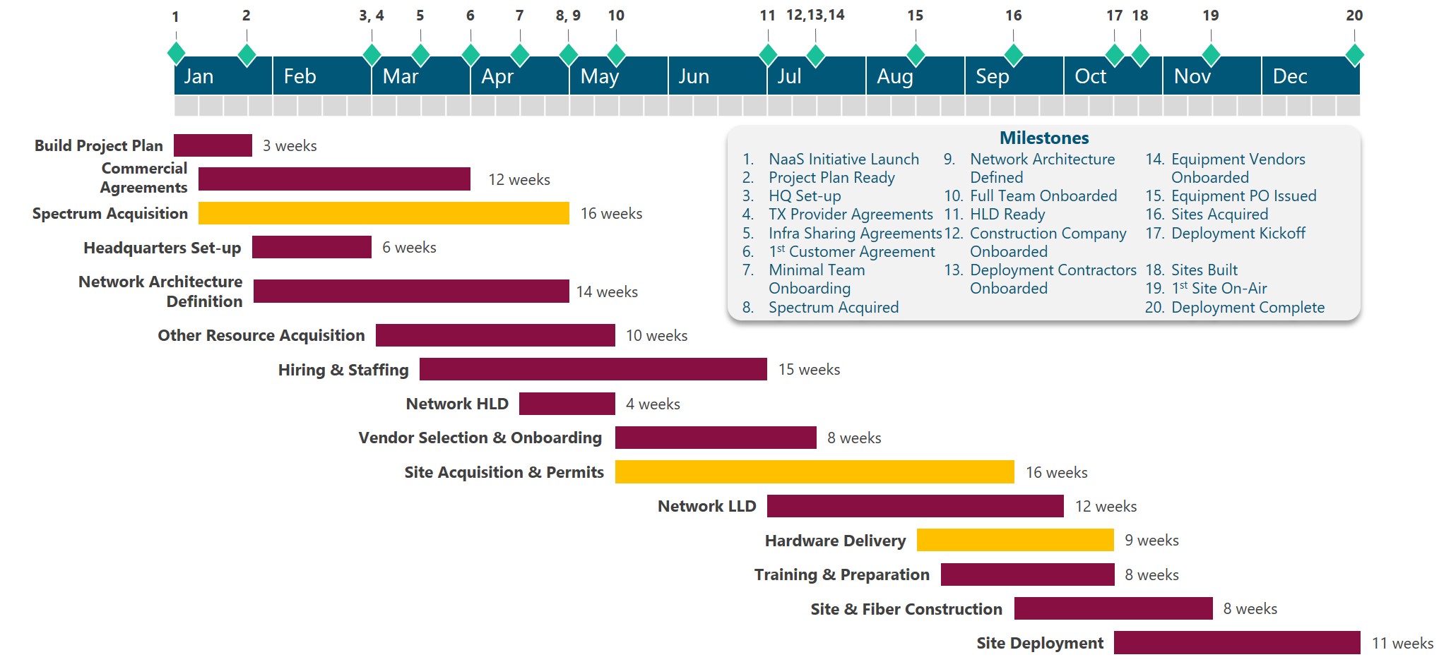
Figure 3. Generic NaaS High Level Schedule.
4.2.3 Schedule Validation
The preliminary Schedule may need to go through several iterations before final acceptance from NaaS stakeholders. These iterations may be triggered by specific constraints, change requests from the executive team, new information related to timelines or status and other factors.
In addition, for each iteration, the Schedule must be validated with respect to the Strategy, achievement of objectives and the Resource Plan. To validate the Schedule the NaaS Operator must answer the following questions:
If an issue is detected, the following techniques and approaches can be put into practice to update the Schedule and/or the Resource Plan.
5 Communications Plan
The Communications Plan is the component of the High Level Project Plan that documents how communications across the NaaS Organization will be structured, implemented and monitored. As mentioned in Section 2.2.4, a well designed and implemented Communications Plan avoids delays and rework due to miscommunication and lack of coordination which is critical for NaaS Operators due to the high cost of re-work and financial constraints that are faced in rural environments.
Sections below present an examination of the required components for an effective Communications Plan, providing guidance for the NaaS Operator to customize reporting mechanisms, communication channels and document management rules and systems.
5.1 Meetings & Reporting Mechanisms
Meetings and reports are valuable means to communicate information and coordinate efforts in any organization. However, they can be a source of overhead reducing efficiency to the overall activities. For this reason, it is important to determine which information and when needs to be communicated through meetings and/or reports.
In the case of meetings, the NaaS Operator can establish periodic and ad-hoc meetings, in addition to strategic governance meetings defined in the Strategy & Scope Module. Periodic meetings have a concrete purpose that require recurrent synchronization within a specific set of stakeholders, and are scheduled in advance with a specific frequency.
Purpose of periodic meetings must be established by the NaaS Operator based on stakeholder needs, management and coordination requirements. Common purposes of periodic meetings are:
Frequency of these meetings will vary based on purpose and the need for collaboration / assessment of the aspects mentioned above. It can be daily (mainly for stand-up check points), weekly, bi-weekly, monthly, or quarterly.
On the other side, ad-hoc meetings are asynchronous in nature and are created based on a specific communication need., such as team coordination, discussion of issues and changes, respond to contingencies (war rooms) and to report results from a major achievement or milestone.
In a similar way to meetings, reports can be scheduled with certain frequency or requested on-demand. Reporting takes time so its important to define efficient methods of reporting to reduce overhead to a minimum, and implement as much as possible ways to automate reports and use portals / cloud applications that allow anyone to dive in the information on their own. Based on the specific requirement reports can be email updates, Project Management assets, Dashboards & Tracking Sheets, slide presentations or spreadsheet reports.
The NaaS Operator must take into account that working in a rapidly changing environment requires communicating these changes more frequently and efficiently. Thus, frequent team checkpoints and updates are required. A set of meeting and reporting rules must be defined by the NaaS Operator. To that end, they can use the Communications Plan Template and the following recommendations:
5.2 Communication Channels
Communication channel plays a key role in how the information is received, processed and utilized by the recipients. Thus, the Communications Plan must establish communication channels to be used across the NaaS Organization, specifying in addition, under which circumstances one of them should be preferred.
Table 4 presents a comparison of typical communication channels which may be used by NaaS Operators to identify communication channels to be considered for their Initiative.
|
Criteria |
Face-to-Face / Meetings |
|
Phone |
Messaging apps |
Video Conferencing |
Enterprise Communication Platforms |
|
Visual/Non-verbal communication |
✔ |
|
|
|
✔ |
✔ |
|
File Sharing |
|
✔ |
|
✔ |
|
✔ |
|
One-to-many conversations |
✔ |
|
|
✔ |
✔ |
✔ |
|
One-on-one conversations |
✔ |
✔ |
✔ |
✔ |
✔ |
✔ |
|
Mobility |
|
✔ |
✔ |
✔ |
|
✔ |
|
Voice |
✔ |
|
✔ |
|
✔ |
✔ |
|
Instantaneous notification |
N/A |
|
✔ |
✔ |
|
✔ |
|
Cross-platform support |
N/A |
✔ |
|
✔ |
✔ |
✔ |
Table 4. Communication Channels
Once communication channels are established, the NaaS Operator may define simple rules to prioritize them based on the following criteria:
In any case it is important that the NaaS Operator promotes direct communication among personnel from all the areas and departments while collaborating, avoiding silos and setting apart hierarchies.
The Communications Plan Template can be utilized by NaaS Operators to document Communication Channels and utilization criteria.
5.3 Document Management
Document management is the set of processes and techniques to create, track and store digital or digitized documents. Usually, a Document Management System (DMS) is used to classify, retain, and protect documents, supporting versioning, collaboration and workflow automation.
For NaaS Operators is imperative to implement some sort of Document Management System, as it offers the following benefits:
Even with the cost associated with these tools, the value that is obtained from them, easily makes up for this cost. To have a simple example, inconsistency in versions can create misinformation, compatibility and lack of coordination that implies loss of time and money which can be solved through the use of these systems.
Table 5 provides a comparison of common Document Management Systems that can be considered by NaaS Operators for implementation in their Initiatives. In addition, small financially constrained NaaS Operators could use free versions of Drive, Dropbox or OneDrive to perform Document Management by sacrificing robustness, support and some integration, workflow and collaboration features.
|
Criteria |
SharePoint (Microsoft 365) |
Alfresco |
Onlyoffice |
Drive1 (G-Suite) |
Dropbox1 |
|
Storage Space |
1 TB |
Flexible |
500 GB |
Unlimited |
Unlimited |
|
Versioning |
✔ |
✔ |
✔ |
✔ |
✔ |
|
Workflows |
✔ |
✔ |
|
|
|
|
Integration with other apps and systems |
Office, ERP, BI, Project Management, Ticketing |
ERP, email, cloud storage and Google Docs |
Cloud storage |
Office 365, Google Docs, Others through APIs |
Office 365 |
|
Online editing |
✔ |
✔ |
✔ |
✔ |
|
|
Device Synchronization |
✔ |
✔ |
|
✔ |
✔ |
|
Deployment Model |
Cloud |
Cloud, On-premise, Hybrid |
Cloud, On-premise, Hybrid |
Cloud |
Cloud |
|
Cost |
$12.5/user/ month |
on-premise: free Cloud / Hybrid: request quote |
Cloud: as low as $1/user/ month |
$12 /user/ month |
$20 /user/ month |
|
Note 1. Unlimited storage available starting at 3 users for Dropbox and 5 users for Drive |
|||||
Table 5. Document Management System Comparison.
Selection and implementation of a DMS is just the first part of the work. For NaaS Operators is important not only to have a Document Management System, but to reinforce best practices around it. The following recommendations are provided as a starting point:
Finally, the selection of the DMS and general rules for its usage can be registered by the NaaS Operator through the Communications Plan Template.
1. RAN – Introduction
The RAN Architecture module provides the NaaS Operator with principles and guidelines that, together, ensure the definition of a RAN Architecture that complies with its service and business requirements.
In addition, an end-to-end process is defined considering a range of implementation options for base stations to be adopted by the NaaS Operator for an optimal RAN Architecture definition.
Through the use of this module, NaaS Operators will be able to generate a Reference RAN Architecture as well as a detailed list of engineering guidelines and equipment requirements to guide subsequent design and deployment tasks to achieve business targets.
1.1 Module Objectives
This module will enable a NaaS Operator to define all architectural aspects regarding the Radio Access Network (RAN). The specific objectives of this module are to:
- Provide a general overview and fundamentals of the architectural options of the RAN in an LTE System.
- Provide guidance for the definition of the RAN Architecture that matches with NaaS Operators requirements, capabilities and business model.
- Enable operators to define engineering guidelines that will serve the RAN design team to generate compliant designs.
- Provide guidelines to generate requirements and specifications that can serve to evaluate and select vendors and specific equipment to be part of the RAN solution.
1.2. Module Framework
The NaaS PlayBook Framework shown in Figure 1 displays the PlayBook Modules and their relationship to the RAN Architecture.
The Strategic Plan & Scope provides business context for the NaaS Operator and serves as a guideline for the definition of the High-Level Network Architecture.
The RAN Architecture module is within the High-Level Network Architecture stream. The generated output of this module will serve as a starting point, scenarios, and constraints definition for the Network Design Modules.
Figure 2 presents a functional view of the RAN Architecture module where the main functional components are exhibited. Critical module inputs are further described and examined in section 2.2. In addition, Section 3 describes aspects for the RAN Architecture definition and organizes them into an end-to-end process to facilitate decision making regarding each component.
Figure 1. Network Deployment and Management Framework.
Figure 2. RAN Architecture Module Functional view.
2. Architecture Fundamentals
General overview of the baseline concepts of the RAN Architecture.
2.1 LTE RAN Architecture & Main challenges
LTE Network is composed by three major elements as shown in Figure 3:
Figure 3. High level view of LTE overall network.
Further details of the overall LTE System Architecture will be presented in the Primer on LTE RAN Architecture Basics.
RAN can be composed by one or more base stations (BTS) distributed over the coverage region. Basic components of a Radio Base station are: Antenna, Radio Frequency (RF) unit (commonly known as Radio Remote Unit or RRU) and the Baseband unit (BBU). These components can be arranged in a couple of ways (configurations) depending on the location of the BBU versus the RRUs and antennas. These configurations are classified into Distributed RAN and Centralized RAN.
Distributed RAN (D-RAN) Architecture
This option reflects the most common architecture in which each BTS is composed by one BBU and one or more RRUs and their corresponding antenna. Interface between BBU and RRUs is known as fronthaul. Each BTS has direct communication to the Core Network via the Transport Network. Figure 4 displays the distribution for a D-RAN.
Figure 4. Basic concept of D-RAN.
Advances in radio design have led to the incorporation of the BBU and an RRU in a single box (all-in-one equipment) located closer to the antenna on the tower or pole. This means savings in both space and energy consumption, reducing CAPEX compared to the traditional BBU+RRU approach. This all-in-one (AiO) approach is a solution commonly used for small cell sites.
Centralized RAN (C-RAN) Architecture
Is an evolution to D-RAN in which every base station is divided into two parts: multiple RRUs and antennas remotely located on each site; each of them managed by a single centralized BBU. Figure 5 displays basic concepts of C-RAN.
Figure 5. Basic concept of C-RAN.
Communication between RRUs and centralized BBU is done via a so-called fronthaul network. Fronthaul network represents a set of elements with strict capacity, latency, and synchronization requirements. Usually, these requirements make necessary the deployment of fiber optic to connect the remote site with the centralized BBUs; in addition, distance between the centralized and the remote sites is constrained as well (Maximum distance between 10 and 40km). Further detail about the Fronthaul Network is provided in the Primer on Cloud RAN Basics.
C-RAN allows NaaS Operator to maintain or increase the number of network access points (RRUs), while keeping (almost) untouched the central BBU. This operating mode is often referred to as the central BBU and is seen as a pool of radio resources for the remote RRUs. C-RAN also allows functionalities that improve network performance by coordinating cells from different BTS. The Coordinated multipoint (CoMP) functionality is a transmission method in which the reception from different cells is tightly coordinated. This results in higher system capacity and improved data rates.
The centralization of a BBU simplifies radio resource management in areas with high concentrations of network users (such as populated towns, transportation stations, large events, etc.) that can put high stress on the base station that serves the area. In these scenarios, the action of adding more D-RAN type sites can increase cost and can lead to signal interference if the base stations are not carefully coordinated.
Although the need of a fronthaul transport network might appear to increase the total cost of ownership (TCO) of the RAN, it has been proved that that a centralized RAN reduces both the CAPEX and the OPEX compared with a traditional RAN.
In addition, some network suppliers offer the possibility of deploying virtualized versions of the physical BBU equipment as Virtual Network Functions (VNFs) to be deployed on a data center together with VNFs corresponding to different network components such as core network components. Virtualization is a technology that is gaining strong interest and popularity in 5G standards and networks. In fact, 5G is a Cloud-native solution that considers must of is components to operate in cloud environments, introducing flexibility to use the same equipment (like data centers) to host multiple virtual elements instead of current function specific equipment.
Deeper insight into the differences between D-RAN and C-RAN and how the integration of cloud RAN is performed will be given in the Primer on Cloud RAN Basics.
D-RAN vs C-RAN Cost Efficiency
C-RAN pools BBU resources, eliminating the cooling and space requirements at the cell site reducing both CAPEX and OPEX due to smaller footprint, lower electricity consumption and fewer maintenance visits.
However, as mentioned before, the use of a C-RAN architecture requires the introduction of a fiber network for the fronthaul transport network. In rural environments, this often represents an investment that is bigger than the savings introduced by the baseband pooling functionality and CAPEX/OPEX savings. In addition, in order to centralized BBUs, the distance between each cell site and the centralized BBU shall not be higher than 40 km.
Thus, in most rural scenarios D-RAN is the best option due to cost trade-offs and distance limitation. C-RAN could be selected in specific urban-like scenarios where the traffic demand is high and concentrated in small areas, ideally where fiber is already available.
Table 1 provides a comparison between C-RAN and D-RAN.
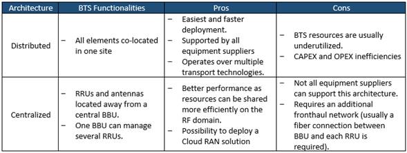
Table 1. Comparison of D-RAN and C-RAN Architectures.
2.2 Radio Access Network Architecture Design Inputs Description
Table 2 presents a description of module input data and candidate sources required for a RAN Architecture definition. Furthermore, the impact of each input on the design process is examined.
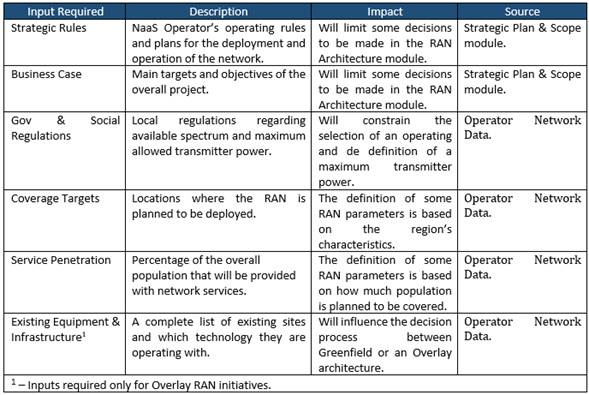
Table 2. Module Input Data.
2.3 LTE RAN Deployment Scenarios
A deployment scenario for the Radio Access Network refers to the available options the NaaS Operator can select to build the base stations. These options depend on NaaS Operator initial conditions and resources as well as service requirements.
While initial conditions determine how the base station is going to be built (as a Greenfield or as an Overlay site), service requirements impact on the type of the BTS (Macro Cell or Small Cell site).
Greenfield & Overlay Scenarios
RAN scenarios can be divided into two main categories depending on NaaS Operator initial conditions:
Both scenarios have their own specifics and challenges to meet business and technical requirements. Deeper insight into this specifics and challenges will be covered in the RAN HLD and RAN LLD Modules.
Macro Cell & Small Cell Sites
Depending on coverage and capacity requirements as well as on geodemographic characteristics of the coverage region, there two main types of BTS that can implemented:
Figure 6 displays the coverage difference between a macro cell site and a small cell site.
Figure 6. Macro Cell Site vs Small Cell Site coverage difference.
Both BTS types provide radio access coverage but in quite different way making each more effective in different situations. Analysis for the selection of one type above the other will be detailed in the RAN HLD Module.
3. RAN Architecture Definition Process
Figure 7 displays the end-to-end process for the definition of the RAN Architecture.
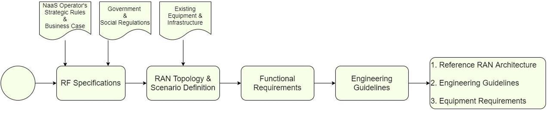
Figure 7. RAN Architecture E2E process.
First step of the definition process is to define the RF Specifications which contemplate the selection of the operating band, guardband definition (in the overlay case) and the maximum allowed transmitter power for all BTSs.
RAN Topology & Scenario Definition section will guide the selection of the BTS architecture, the deployment scenarios, the BTS type(s) (Macro cell or Small cell) to be considered. It also provides guidance for the evaluation of a Demarcation point between the RAN and the core network in case NaaS Operator is not deploying its own core network.
Functional Requirements will define the required network functionalities based on RAN Sharing schemes and VoLTE if it applies.
Finally, the Engineering Guidelines Definition section will provide the NaaS Operator instructions on how to define engineering rules to be considered during the design process.
3.1 RF Specifications
BTS operation is conditioned to multiple parameters. These parameters are:
These parameters must be selected based on NaaS Operator service requirements, available resources, and countrys policies and regulations.
In this section, guidance for the selection of the mentioned parameters is provided.
3.1.1 Spectrum Definition
Electromagnetic spectrum is a limited resource that is managed by a regulatory body in each country. For this reason, the selection of an appropriate spectrum band and carrier bandwidth depends on factors such as the country’s regulatory policies, spectrum fees, available spectrum chunks, MNO partners spectrum position and unlicensed spectrum conditions.
In addition, for Overlay scenarios it is necessary to set guard bands between LTE and existing 2G and 3G technologies in order to avoid interference between the co-located systems and a degradation in the service.
Band Selection
NaaS Operator can select its operating band based on one of the following considerations:
- Re-farming (OVERLAY SCENARIO): LTE system can operate over existing 2G GSM and 3G UMTS bands (e.g. Band 3: 1800MHz or Band 8: 900MHz) in overlay scenarios. As a result, operators can re-farm parts of the spectrum currently used for 2G or 3G voice and data services to support LTE. Spectrum re-farming is a cost-effective way to increase capacity in existing networks without the need to bid for new spectrum and by reutilizing infrastructure to overlay LTE. However, the only way re-farming is feasible is when the NaaS Operator or its partners/customers have enough contiguous spectrum (this means that the operating frequency band has enough spectrum left to insert a new carrier) to allow simultaneous operation of two or three technologies in a frequency band.
- Leverage from partners spectrum: NaaS Operator can use the spectrum previously assigned to its partner (in case partner has already been assigned a 4G band).
- Use an Unlicensed band: Electromagnetic spectrum is a scarce resource that is regulated and assigned by each country governmental institutions. However, the utilization of unlicensed spectrum in the 5GHz range has been gaining interest in past years because it allows an operator to deploy LTE services without the necessity of bidding for a licensed spectrum. On the other hand, the use of unlicensed spectrum imposes transmission power limitations, which limits coverage area of the BTS. In addition, NaaS Operator needs to verify if other operations are using unlicensed spectrum in the area, as this may cause a considerable amount of interference. NaaS Operator can find additional information about unlicensed bands for LTE in the Primer for LTE in Unlicensed Spectrum. NaaS Operator must be aware that the operation of LTE in unlicensed spectrum may not be supported by all user devices.
- Get Spectrum from government: NaaS Operator can bid to be assigned an LTE band following country regulations. Moreover, some countries around the world have been interested in facilitating unused spectrum to service providers that are willing to bring mobile services to uncovered populations (see Rhizomatica initiative). NaaS Operator can see if this same principle applies in its own environment.
Spectrum bands differ from each other in terms of their usage (for coverage or for capacity), available bandwidth, clutter type (Rural Urban) and if they are paired (block of spectrum in a lower frequency band and an associated block of spectrum in an upper frequency band) or not.
From a usage point of view, low frequencies (< 1GHz) provide extended network coverage at lower cost as fewer base stations are required to achieve greater geographic coverage. On the other hand, Higher frequencies (>1 GHz) are primarily used to cover urban and suburban areas where data traffic is dense and substantial network capacity is required (higher spectrum bands normally provide larger bandwidths which allow for larger transmission rates). Figure 8 shows spectrum bands usage from a coverage and capacity point of view.
Figure 8. Coverage and Capacity characteristics of spectrum bands.
NaaS Operator can leverage on Table 3 to choose a band that best fits its business strategy.
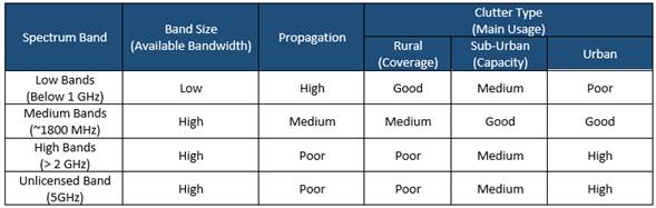
Table 3. LTE bands main characteristics.
LTE spectrum can operate in a wide range of bandwidths: 1.4, 3, 5, 10, 15, or 20 MHz.
If the NaaS Operator has the opportunity to select an specific LTE spectrum band for a rural network deployment, it is recommended to aim for a low band (below 1GHz) and a bandwidth that covers its present and future necessities in terms of coverage and capacity.
Cell bandwidth of 20MHz is often used in urban and suburban environments in which capacity is the focus. However, having a 10MHz bandwidth can be a good tradeoff between coverage and capacity performance. A 5MHz bandwidth can be useful to bring connectivity to an uncovered population but will be limited in terms of capacity performance. Having large bandwidths (e.g. higher than 20MHz) introduces the possibility for a capacity expansion using a second carrier.
For instance, in recent country-wide rural projects, most mobile network operators (MNOs) and NaaS Operators have selected Band 28 700MHz and 10MHz cell bandwidth as this combination has proven to perform good to provide rural coverage.
Guard band Requirements (OVERLAY SCENARIO)
One of the important aspects when introducing the LTE system on top of existing systems like 2G-GSM or 3G-UMTS is the guard band requirement. More specifically, when LTE is co-located with other technologies in the same site where nearby antennas or sharing scenarios are adopted then a guard band needs to be maintained to avoid interference between collocated systems.
The guard band requirement can be summarized as follows:
Figure 9. Guard band requirement for collocated LTE and GSM systems in the same band.
Table 4 summarizes the guard band requirement for LTE with different collocated technologies.
|
Co-existing systems |
Required Guardband |
|
LTE band X + GSM band X |
0.2 MHz (One GSM carrier) |
|
LTE band X + LTE band Y |
0 MHz |
|
LTE band X + UMTS band X |
0 MHz (RRU must implement a strict RF filter to avoid interference) |
|
LTE-FDD + LTE-TDD |
Half of the channel BW (the higher one) |
|
LTE band X + LTE band X |
0 MHz |
Table 4. Summary of guard band requirements.
3.1.2 LTE Duplexing Scheme Selection
LTE has two schemes for resource sharing and achieve two-way communication (between the eNodeB and the UE): Frequency Division Duplexing (FDD) and Time Division Duplexing (TDD). FDD scheme uses one frequency for downlink (DL) and another frequency for uplink (UL); allowing simultaneous communication between BTS and UE. On the other hand, in TDD scheme both BTS and UE use the same frequency for their transmissions, preventing simultaneous communication and implementing a dedicated time slot for transmission (TX) and for reception (RX). Figure 10 shows the operation of FDD and TDD schemes.
Figure 10. LTE Duplexing Schemes.
NaaS Operator must be aware that the Duplexing scheme also depends on the operating band. In case the selected (available or allocated) frequency band differs from the chosen duplexing scheme, NaaS Operator will be tied to work with the scheme associated to that band.
Table 5 shows a comparison of the FDD and TDD schemes from transmission rate, coverage, and CAPEX performance points of view. NaaS Operator can use this criterion to choose the scheme that best fits its service requirements.
|
Performance Item |
FDD – LTE |
TDD – LTE |
|
Transmission Rate Performance |
FDD allows higher throughputs. |
Transmission rates cannot be achieved at similar distances when compared to FDD. However, it allows the implementation of advanced antenna techniques such as beamforming. |
|
Site Count |
Since FDD achieves cell edge rates at farther distances, the number of sites required to serve a given area is lower than TDD. |
In a system comparison using the same frequency band, the TDD system requires 31% more base stations than FDD when using a 1:1 (same number of RX and TX slots) and 65% more base stations when using a 2:1 (twice the amount of RX than TX slots) due to capacity constraints. |
|
Spectrum Arrangement |
FDD operation requires twice more spectrum for a single LTE carrier for a given channel bandwidth. |
TDD can operate in an unpaired spectrum. In addition, it can also be suitable for asymmetric transmission demands (like fixed wireless access deployments). |
|
CAPEX |
The fact that FDD requires fewer BTSs to serve a specific area using the same frequency allows the NaaS Operator to incur in lower equipment and infrastructure associated costs. On the other hand, FDD spectrum fees can make it a more expensive option. |
|
Table 5. FDD vs TDD performance comparison.
3.1.3 Transmitter Power Definition
Together with the operating band, the maximum transmitter power (per antenna port) is one of the most important parameters to be considered previous to the design step. BTS transmission power must be set based on the following considerations:
|
BTS Type |
Radiated Power |
|
Medium Range (Small Cell) BTS |
Up to 10W (40 dBm) |
|
Wide Area (Macro Cell) BTS |
There is no upper limit for the radiated output power of a Wide Area (Macro Cell) BTS |
Table 6. BTS classification based on transmitter power.
For the case of small cells, most equipment in the market can achieve 10W (40 dBm) as maximum transmission power. In MORAN scenarios (as will be discussed in section 3.3.1) a 10W small cell can allow the implementation of two independent 5W carriers (one per Mobile Operator). This rule should be always considered for small cell definition because increasing the power with small transmitter heights has diminishing returns.
For transmit power ranges above 10W, network design should consider a macro cell site for the design process. Maximum power can be set according to the following point.
|
Transmitter Height |
Maximum Allowed Transmit Power |
|
< 10m |
<= 10 W |
|
From 10m to 20m |
10W to 20 W |
|
From 20m to 30m |
20W to 30W |
|
> 30m |
>= 30W |
Table 7. Tower height and Maximum Allowed Transmitter Power relation example.
3.2 RAN Topology & Scenario Definition
This section guides NaaS Operator on its way to standardize the topology that will be implemented on the RAN considering possible scenarios which include:
3.2.1 D-RAN vs C-RAN Definition
As shown in Table 1, there are several tradeoffs that must be considered when selecting between D-RAN and C-RAN. In addition, this selection will condition several aspects of the overall network, mainly transport and core design and infrastructure.
Despite being a promising solution in terms of performance management and future-proof, C-RAN is feasible only in a reduced number of scenarios. Considering this, the decision process of selecting between D-RAN and C-RAN can be reduced to the following points.
Methodology to select between a D-RAN or C-RAN architecture is shown in Figure 11:
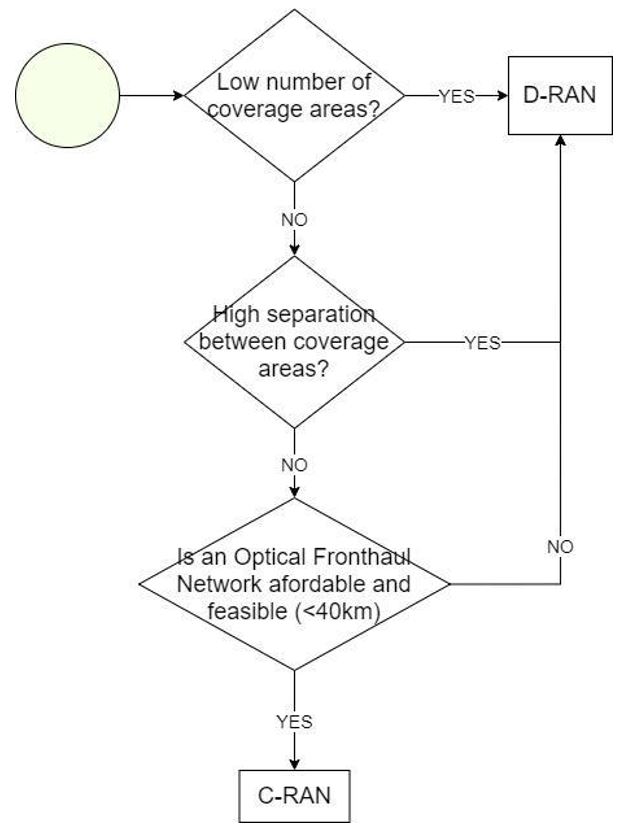
Figure 11. Methodology to select between a D-RAN or C-RAN architecture.
3.2.2 Greenfield / Overlay Scenarios Identification
NaaS Operator can Identify its initial scenarios considering the following points:
Figure 12 displays a methodology to identify which are the initial scenarios in a NaaS Operator environment. NaaS Operators network can be composed by a combination of Greenfield and Overlay sites if conditions are met.
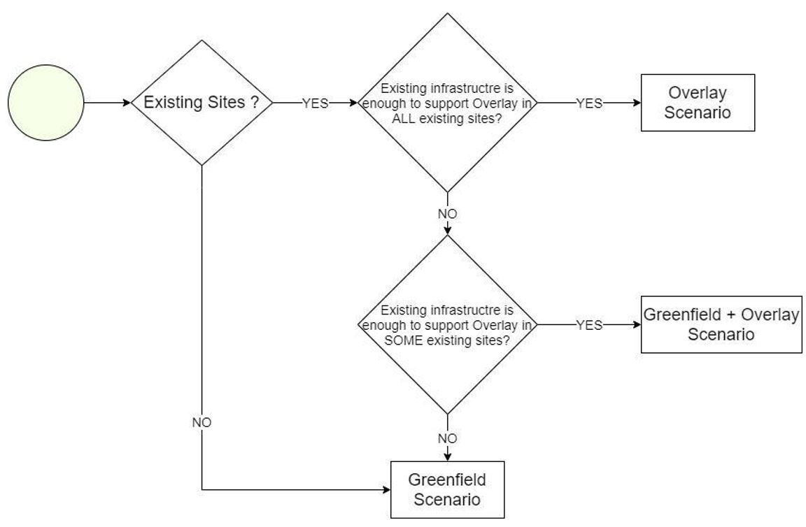
Figure 12. Methodology to select between Greenfield and Overlay scenarios.
Existing sites must be able to accommodate new infrastructure (BBU, RRUs or antennas) to be considered as Overlay ones. This means that they must contain enough space on the towers and power sources to install and feed the new equipment. A site survey should be held in order to evaluate if existing sites are candidates for an overlay deployment. The RAN HLD Module provides a questionnaire for the evaluation of existing sites in order to define whether they can be used for an overlay or not. This evaluation must be held by a site survey to the desired site. Details for the site survey will be given in the Site Survey Module.
3.2.3 Macro / Small Cell Scenarios Definition
The NaaS Operator network can be composed of a combination of macro cells and small cells. Table 8 displays a technical comparison between Macro Cells and Small Cells.
|
Macro Cell BTS |
Small Cell BTS |
|
|
Main purpose |
Coverage and capacity |
Additional Capacity and cover small targeted areas. Can be selected if Macro Cell BTS is too expensive. |
|
Transmit Power |
Up to 80W (depending on equipment suppliers capabilities) |
Up to 10W |
|
Cell Coverage |
~5 10 km |
~2 5 km |
|
Site Solution |
BBU + RRU + Antenna |
All-in-One equipment. Integrated BBU and RRUs (in some cases, antennas can also be integrated into the same box. |
|
Antenna Configurations |
2×2, 4×4 MIMO |
2×2 MIMO |
|
Installation options |
Tall towers (10m 40m) Rooftops |
Small towers (up to 10m) Lamp poles Rooftops |
Table 8. Macro Cell and Small Cell BTS technical comparison.
This decision-making process of selecting BTS Types must take into consideration several conditions ranging from technical, infrastructural and financial constraints to population distribution and traffic behavior. The combination of these conditions may raise the appearance of multiple scenarios that will vary from one region to another. Table 9 displays a scenario definition based on population classification.
|
Town Size |
Population Density |
Separation between Towns |
|
Small |
Low |
High |
|
Small |
High |
High / Low |
|
Big |
Low |
High / Low |
|
Big |
High |
Low |
Table 9. Scenario definition.
Multiple scenarios may bring the necessity to consider a wide range of BTS Types and configurations.
However, in order to have a homogeneous network (which will simplify future processes like site catalog, network construction and maintenance, among others), NaaS Operator can reduce all possible BTS configurations into a few options. While having a low number of configurations might limit performance, it allows for a cost-effective and easy operation of the network.
Naas Operator can provide BTS configurations as shown in Table 10 to be considered for all its network. Design team will decide (during the HLD process) which option best suits a specific area.
|
BTS Type |
Number of sectors per BTS |
Tower Hight |
|
Small Cells |
– 1 sector (omni) |
Indistinct |
|
Macro Cells |
– 1 sector (directional) (Only for highway coverage) |
Indistinct |
|
– 2 sectors (directional) |
10m to 20m |
|
|
– 3 sectors (directional) |
> 20m |
Table 10. Number of sectors definition per BTS type.
3.2.4 Demarcation Point
Demarcation point in a network divides it into two or more sections (depending on the number of demarcation points). For instance, the S-GW acts as a demarcation point between the RAN and the core network.
Demarcation point in the RAN is required if the core network is not maintained/owned by the NaaS Operator. The Demarcation point allows to have control over RANs performance and to perform charging activities to its customers that are Mobile Operators. If the deployment of a mobile core is considered as part of the architecture, then, the demarcation point is the SGW or PDN Gateway. On the other hand, if there are no plans for a mobile core, then a demarcation point must be considered in the RAN.
The following are some functionalities introduced by a demarcation point in the RAN:
Some demarcation points that can be implemented in the RAN are:
This gateway (GW) improves management and performance operations in multi-RAT or multi-MNOs scenarios. Additional functionalities introduced by the RAN GW are:
The RAN GW general concept is shown in Figure 13.
Figure 13. RAN Gateway concept.
An IPsec GW can be introduced to provide IPsec tunneling termination towards RAN and towards core network, thus, improving network security for all parties in the network. IPsec GW concept is displayed in Figure 14.
Figure 14. IPsec Gateway concept.
NaaS Operator must be aware that demarcation point functionalities may vary from one equipment supplier to another.
3.3 Functional Requirements
This section will guide the NaaS Operator in the definition of the RAN functionalities required for the operation of the defined topology and service requirements defined as part of the NaaS Operator business strategy.
3.3.1 RAN Sharing Scenarios Definition
NaaS Operator central strategy is to enable business to MNOs in new areas without them having to invest on network infrastructure. Instead, MNOs can provide their network services using NaaS Operators infrastructure and network resources.
NaaS Operator can provide its RAN infrastructure to multiple MNOs based on the following sharing schemes:
NaaS Operator can use Table 11 to decide which sharing scheme best fits its strategic plans.
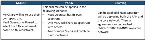
Table 11. RAN Sharing application schemes.
Figure 15 illustrates the implementation of each RAN sharing scheme.
Figure 15. Possible RAN Sharing Schemes.
Table 12 summarizes technical characteristics of each scheme.
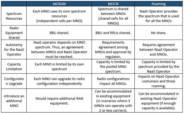
Table 12. RAN Sharing schemes characteristics.
3.3.2 VoLTE Implementation Evaluation
Voice over LTE (VoLTE) is the 4G-LTE solution to provide voice services in an LTE network. VoLTE provides high-quality voice and video services. However, this section only applies if at strategy level the NaaS Operator has decided to provide voice services.
The implementation of VoLTE on a network brings the following requirements:
These requirements represent an addition to the networks CAPEX, increasing NaaS Operator investment. Additionally, the configuration of VoLTE on a BTS means extra integration efforts.
However, NaaS Operator can avoid the implementation of VoLTE if LTE BTSs are deployed as an overlay in locations where existing 2G and/or 3G sites are already operating. Voice in overlay scenarios can be carried by the existing RATs using the Circuit Switched FallBack (CSFB) functionality which allows an user equipment (UE) connected to the LTE system to move to 2G-GSM or 3G-UMTS in order to complete the voice communication. Once the voice call is over, the UE returns to LTE. CSFB principle is shown in Figure 17.
Figure 16. Circuit Switched FallBack principle.
For these reasons, the implementation of the CSFB functionality is preferable from financial and sites configuration points of view. However, CSFB principle does not apply in cases where there are no existing sites operating with 2G and/or 3G. In other words, VoLTE is the only option to provide voice services on Greenfield Scenarios.
Figure 17 displays a strategic criterion to guide NaaS Operator in the decision-making process of deploying VoLTE:
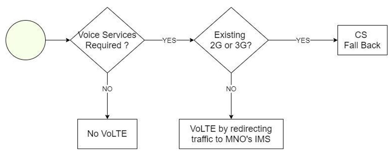
Figure 17. VoLTE decision-making process.
3.3.3 Equipment Requirements Definition
Network equipment chosen for the deployment of the RAN must be able to support the selected architecture that has been established up to this point and will depend on the BTS Type: Macro Cell or Small Cell.
In addition, RAN features must be considered too in order to allow the implementation and operation of the defined RAN Architecture and functional requirements that have been established up to this point.
Table 13 summarizes equipment requirements and RAN features required based on defined RAN Architecture requirements.
NaaS Operator can use the RAN Equipment Requirements Template to create its own version.

Table 13. Equipment requirements based on RAN Architecture specifications.
3.4 Engineering Guidelines Definition
Engineering Guidelines are a set of rules that need to be followed during the High-Level Design (HLD) Process. Engineering Guidelines must be set according to the defined RAN Architecture and should cover the minimum requirements for the network to operate as desired. Network designer will establish site configurations based on the given rules. These rules cover Radio (coverage and capacity) as well as Infrastructure aspects of the network.
NaaS Operator can use the e the Engineering Guidelines Template to set the engineering rules to be considered during the HLD process. Recommended values will be given for each parameter as a starting point for the NaaS Operator.
3.4.1 Coverage & Capacity Guidelines Definition
Guidelines for the radio aspects of the network include parameters that must be considered during network dimensioning. Table 14 summarizes the required Coverage and Capacity parameters that must be set before the HLD process (additional parameters will be introduced and explained in the RAN HLD Module).
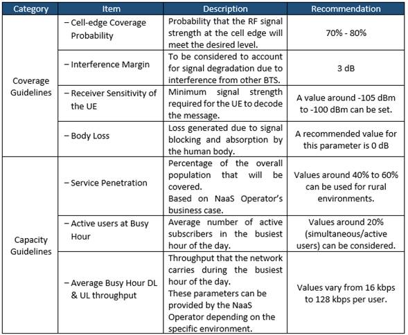
Table 14. Description of Coverage and Capacity engineering rules categories.
3.4.2 Infrastructure Guidelines Definition
Guidelines for the infrastructure aspects required to build site configurations during the HLD process. Table 15 summarizes the categories of the infrastructure engineering rules:
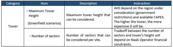
Table 15. Description of Infrastructure requirements categories.
4. RAN Architecture Report
A RAN Architecture report must be elaborated in order to provide a clear image of the overall network and engineering guidelines to the design team. Additionally, equipment requirements can be considered for the RFx process.
The report must cover all points and considerations that define each BTS in the RAN and its main functionalities. Such points are:
NaaS Operator can use the RAN Architecture Report template as a reference to create its own version.
Annex I
Table 16 illustrates the supported bands Frequency Division Duplex (FDD) LTE while
Table 17 illustrates bands for Time Division Duplex (TDD) LTE according to the 3GPP.
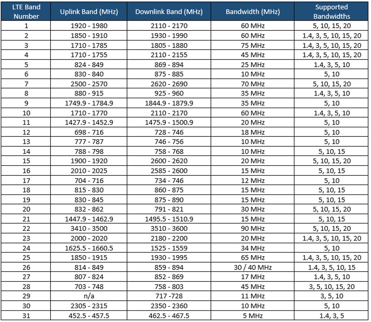
Table 16. FDD-LTE 3GPP Bands.
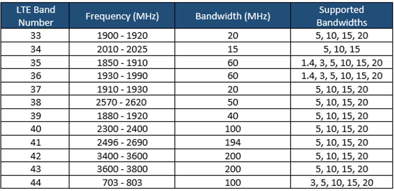
Table 17. TDD-LTE 3GPP Bands.
1. Transport and IP Architecture Introduction
This Transport and IP Architecture module aims to provide a frame of reference and enable a NaaS operator to define the overall network solution that interconnects the radio access network (RAN) toward the mobile core and data centers, including the technical aspects of the IP networking solution.
This module provides an overview of the transport and IP network fundamentals focusing on required functional and operational aspects to support the LTE service. Moreover, it provides guidelines to translate these requirements into a transport and IP architecture that better suits NaaS operator capabilities and constraints.
The output of this module is the transport and IP reference architecture that includes the overall solution description, as well as a formal requirements specification to guide subsequent design and vendor selection phases.
1.1 Module Objectives
This module will enable the NaaS operator to define the reference architecture of the mobile transport and IP network. The specific objectives of this module are to:
- Provide an information base and fundamentals of the architectural elements of the transport and IP network.
- Guide the NaaS operator to determine the transport and IP architecture functional and operational requirements to provide an LTE service.
- Provide instruction to define and specify the most appropriate transport and IP network architecture according to the NaaS operators requirements, capabilities, and business model.
- Provide guidelines to generate a consolidated reference architecture and requirements specification for evaluation and vendor selection for the transport and IP network.
1.2 Module Framework
The NaaS playbook framework in Figure 1 describes the structure, interactions, and dependencies among disparate NaaS operator areas.
The Strategic Plan & Scope provides business context for the NaaS operator and serves as a guideline for the definition of the high-level network architecture, which in turn drives the strategic decisions to forthcoming phases.
The Transport & IP Network Architecture module is included within high level architecture and has direct relation with RAN and mobile core architecture as well as network monitoring architecture. The generated output of this module will serve as a required input for the network design modules.
Figure 1 Module framework
The transport and IP network architecture functional view is shown in Figure 2, where the main components are depicted in addition to inputs that drive the definitions made throughout the development of the transport and IP reference architecture.
Figure 2 Transport and IP architecture framework
The model structure is divided into four sections. Section 1 provides an overview and fundamentals involved in the design of the transport and IP architecture. Section 2 focuses on the functional and operational requirements of the transport network. Section 3 discusses possible variations to implement the transport and IP network and methodologies to perform the selection that best suits NaaS operator conditions. Section 4 illustrates how to integrate previous elements into a formal reference architecture and requirements specification.
2 Transport and IP Network Architecture
General overview of transport and IP network architecture and main transport technologies to be implemented in the network. In addition, the particularities of the IP network are examined.
2.1 Transport Network Overview
In a mobile environment, the transport network interconnects disparate networks, including the RAN, data centers, and external networks. Figure 3 displays the architecture of a typical transport network.
Figure 3 Typical mobile network architecture
Mobile networks are ubiquitous and support a mix of traffic types originating from and terminating to mobile devices. All this traffic must be conveyed between the mobile cellular base stations through the transport network up to the mobile core.
For this reason, different segments exist on the transport network that for most of NaaS operators can be classified as: last-mile and aggregation level. Additionally, there might exist a connection provided by a third-party network, which can provide the last mile or aggregation. The network segments are mostly defined by the technology and topology used within it. The key network segment characteristics are:
Figure 4 displays the structure of the transport network.
Figure 4 Basic structure of a mobile transport network
The structure displayed in Figure 4 considers different physical technologies and topologies. Moving left to right, the last-mile connects a demarcation device, usually deployed at the cell site, to a first stage of traffic grooming and concentration. The aggregation network, in turn, further aggregates traffic, adapts any technology change and provides the hand-over point to a higher level of aggregation network.
The term physical connectivity is used to represent any technology that can be used to connect nodes. Common physical connectivity includes fiber optic, microwave, and satellite links. In addition, on top of the physical layer a networking layer is implemented that embraces all the possible logical architectures needed to steer LTE traffic and applications.
2.1.1 LTE Flattened Transport Architecture
Traditional cellular networks (e.g., 2G and 3G) are hierarchical in nature; that is, there is no direct communication between the base station and the core elements. Base stations communicate with their respective radio controllers that are in turn connected to the core elements.
Long-term evolution (LTE) defines a flat network architecture that eliminates the radio controllers. Thus, controller functions are redistributed to the core elements and the base stations (eNodeB). For this, two logical S1 interfaces between the eNodeB and the evolved packet core (EPC) are implemented: the S1-MME to the mobility management entity (MME) and the S1-U to the serving gateway (S-GW). MMEs handle authentication and signaling aspects of the mobility management control plane. S-GWs terminate the user plane traffic. Figure 5 illustrates the LTE network architecture:
Figure 5 LTE flattened transport architecture
Figure 5 illustrates an overview of the logical planes needed in the transport network. Various kinds of user and control planes are transported across the transport network. In addition, management traffic that consists of the data needed for support of the network elements FCAPS (fault, configuration, accounting, performance, security) must be considered. When synchronization is arranged by the transport network (e.g., precision time protocol (PTP)), these packets need to be delivered to the eNB from the timing server.
2.2 IP Network Overview
On top of the physical media, the connectivity required by LTE can be realized by using different service types. All these traffic types are forwarded from the last-mile through the aggregation tiers to the core.
The most common implementation scenario including last-mile/aggregation and third-party network segments is displayed in Figure 6:
Figure 6 Transport network scenario based on carrier Ethernet with L3VPNs
The scenarios presented in Figure 6 have been defined only on top of Ethernet (IEEE 802.3), as its the dominant layer 2 technology. The use of Ethernet interfaces has also been assumed for all base station and mobile core nodes. More detail on the required transport protocols can be found in Section 4.4.
In the third-party network segment, an IP/MPLS-based transport is used to implement a L3 VPN on top of Ethernet. Using a L3 VPN permits the NaaS operators nodes to communicate privately over the third-party network, even though it routes through multiple third-party elements. Detail on this implementation is out of scope for this module, as that is a service provided by the third-party network.
2.3 Transport Technology Overview
The implementation of 4G LTE imposes some requirements on transport networks, such as more network capacity and latency reduction. These requirements are better served through terrestrial technologies (fiber optic and microwave). But in rural areas this becomes a challenge because satellite transport is usually the only feasible technology. For this reason, the transport network infrastructure is an essential component of the NaaS operator network.
An overview of commonly used technologies in the transport network is presented in the following subsections.
2.3.1 Fiber Optic Technology
Fiber optic is the mainstay wired transport in mobile operator networks whenever its available because of its significant, inherent bandwidth carrying capability. Additionally, several additional techniques can be used to offset any bandwidth constraints and essentially render the fiber assets future-proof.
While fiber optic has tremendous operational capacity, its main limitation is the cost and logistics of deployment. Moreover, it can take several months to provision each cell site with fiber optic transport.
The fundamental aspects of fiber optic technology design are discussed in the Primer on Fiber Optic Technologies Principles.
2.3.2 Microwave Technology
Most operators rely heavily on microwave transport solutions in the 5 GHz 80 GHz bands (frequencies above 15GHz are not generally feasible in rural environments). Microwave is a low-cost option for mobile transport, as it can be deployed in a matter of days and support a range of up to several tens of kilometers.
The main limitation of microwave links is the requirement of line of sight (LOS) between transmitter and receiver. This represents an important constraint for its implementation, especially in rural areas due to steep conditions in the terrain. In addition, in many cases microwave requires a license to operate. In high frequencies, microwave links are subject to atmospheric effects or rain fade, which can attenuate the signal and limit its range.
The fundamental aspects of microwave technology design are discussed in the Primer on Microwave Technologies Principles.
2.3.3 Satellite Technology
Satellite technology is deployed in fringe network areas, usually in rural scenarios in emerging markets. Furthermore, satellite technology can be deployed as a temporary measure as an operator waits for regulatory microwave licenses to be approved. Satellite coverage is determined by satellite footprint and location-specific geographical and meteorological conditions.
The cost of satellite terminal equipment located at the base station is in line with microwave equipment. However, the OPEX burden generated by the satellite service fee can impact on the business case.
The fundamental aspects of satellite technology design are discussed in the Primer on Satellite Technologies Principles.
3 Functional & Operational Requirements
Examination of functional and operational characteristics of the transport and IP network, providing guidance and general criteria to establish requirements for network designers and solution providers.
3.1 Transport Network Planes
As stated in section 2.1.1, each eNB requires connectivity to the core elements and additionally for network management and potential synchronization. The subsequent sections describe the different planes that must be supported by the transport network. More detail on required transport protocols can be found in Section 4.4.
3.1.1 User plane
The user plane (U-plane) in the LTE transport network consists of the S1-U plane used to transport user data between the eNodeB and the S and P-GW using a general radio service tunneling protocol user (GTP-U). It also includes the X2-U plane used to provide connection to neighbor eNodeBs.
The protocol stack required to support the user plane is shown in Figure 7.
Figure 7 LTE user plane protocol stack
3.1.2 Control Plane
The control plane (C-plane) in the LTE transport network is comprised of the S1-MME traffic used to transfer signaling information between the eNodeB and MME. This information is used for S1 bearer management, mobility, and security handling, as well as for application signaling messages between the user equipment (UE) and MME. It also includes the X2-C plane used to provide connection to neighboring eNodeBs.
The protocol stack required to support the control plane is shown in Figure 8.
Figure 8 LTE control plane protocol stack
3.1.3 Management Plane
The management plane (M-plane) in the LTE transport network is the interface between the eNodeB and the O&M system. The M-plane consists of all data required to manage and monitor the status of the network elements. The volume of this traffic has to be considered during the capacity analysis and the frequency to collect these data.
The protocol stack required to support the management plane is shown in Figure 9.
Figure 9 LTE management plane protocol stack
3.1.4 Synchronization Plane
The synchronization plane (S-plane) in the LTE transport network is important to ensure proper functionality of the eNodeBs. The two types of synchronization methods for a mobile network are phase/time and frequency. More detail on the synchronization requirements is in Section 4.7.
However, the implementation of this plane can be optional if its decoupled from the transport network by using GNSS (global navigation satellite system) solutions at the eNB.
3.2 Availability & Resiliency
Most of the design considerations for the transport network architecture are constrained by network ability to meet the proper levels of availability (proportion of time a system is in a functional condition) that is supported by means of resiliency (ability to readily recover). Table 1 shows the downtime per year according to the availability value.
|
Availability |
Downtime Per Year |
|
99% |
3.65 days |
|
99.9% |
8.76 hr |
|
99.99% |
52 min |
|
99.999% |
5 min |
Table 1 Availability and corresponding downtime per year
NaaS operators must define different availability levels for the transport network according to network segment (last-mile/aggregation). Figure 10 displays typical values of availability and resiliency requirements across the transport segments.
Figure 10 Availability on each segment of transport network
As seen in Figure 10, availability requirements of the transport network are derived from the availability requirements of the end-user service. A typical requirement for the transport network in a rural environment could be an availability value of 99.95%. In most cases the availability is dominated by the last-mile link.
Recommended values for the various segments within the rural NaaS transport network are presented in Table 2.
|
Service Level |
Availability (%) |
|
Last-mile Link |
99,9% |
|
Aggregation Link |
99,99% |
|
3rd Party Network |
99,99% |
|
Satellite Link |
99,9% |
Table 2 Availability requirements definition example
3.3 Quality of Service Support
Quality of service (QoS) management is essential to distribute limited resources between different traffic classes. The concept of QoS used in LTE networks is based on classes, where each type of traffic (e.g., data, voice, signaling) is assigned a QoS class identifier (QCI) by the network to ensure adequate QoS for carrier traffic in the LTE network.
To allow separation of traffic in the transport network, translation of the radio QCI level into the transport QoS level is performed initially on the eNodeB. However, additional translations may be performed by intermediate transport devices along the path. For this reason, the QoS parameters in all the devices across the path must be correctly configured.
To allow traffic separation, the IETF introduced the notion of differentiated services (DiffServ) classes as a layer 3 mechanism. The key idea is to mark the priority traffic so that it isnt affected by possible congestion due to the fluctuation of link usage level. The DiffServ concept is a priority marking scheme carried in the IP header.
Layer 2 QoS mechanisms are used when the traffic traverses L2-only devices (e.g., microwave radios). These devices use two 2-byte fields, tag protocol identifier (TPID), and tag control information (TCI) to mark packets with the corresponding service type.
Figure 11 displays the QoS mechanisms used in LTE network. The traffic type at the radio level is managed by the QoS class identifier (QCI). The operator defines the rules in the eNodeB by means of a QCI mapping table containing a one-to-one mapping from the QCI value to the DSCP flag value and L2 QoS codes. Then, the intermediate device uses the QoS values to treat the traffic according to their capabilities (i.e., L2 or L3 QoS mechanisms).
Figure 11 QoS mechanisms in LTE networks
Its recommended that the NaaS operator ensure that traffic is classified and marked as close as possible to its origin. In most of the cases these tasks are performed by the eNode B for the uplink traffic and by the core elements for the downlink traffic. Additionally, all the intermediate nodes must maintain the QoS markings. Its highly recommended that at least 4 different classes of traffic are defined to be used on the transport network.
4 Transport and IP Architecture Design Considerations
Analysis of multiple implementation options to be considered in the overall solution. In addition, methodologies for the most appropriate selection are provided.
4.1 Transport Technologies Selection
This section describes the architecture of different transport technologies to be used on the transport network. Moreover, it describes implementation alternatives for each technology and general guidelines to select that which is most appropriate.
4.1.1 Fiber Optic Transport Considerations
The general architecture using fiber optic as a transport technology is displayed in Figure 12. Here, the enodeB is connected to a router located at the site, commonly named as cell site gateway (CSG), which provides the transport services. The CSG is connected through a fiber link to the aggregation node located in the transport node, which sends the traffic to the mobile core. Alternatively, an L2 switch can be deployed on the cell site location, moving the CSR location to the aggregation node.

Figure 12. Transport architecture using fiber optic
For the implementation of the fiber optic architecture, three scenarios are identified for NaaS operators:
In the following sections, the primary considerations for the two first scenarios are examined, and engineering guidelines are provided accordingly.
4.1.1.1 Fiber Construction
This scenario considers creating a fully dedicated, private physical network infrastructure by the NaaS operator. This approach can easily scale to handle whatever bandwidth requirements arise in the future.
On the other hand, the construction cost in rural areas is high, which may impact the overall CAPEX project. Additionally, construction time can be lengthy and requires extensive planning and project management.
The principal considerations to support the fiber infrastructure design process are described in the following subsections.
Right of Way Definition
A right of way provides the right to pass across the lands of another, usually in a strip, acquired for or devoted to building facilities such as roads, railroads, or utilities. In this sense, rights of way are closely interrelated with both civil work for fiber infrastructure and technical engineering for network planning, operation. and maintenance.
For the reasons stated above, a right of way definition must be established to prioritize the types of road (e.g., main roads, highways, electrical lines) that may be considered during later phases in the transport network design. For example, a NaaS operator can only be granted to construct fiber infrastructure in rural roads, so other types of roads (e.g., highways) must not be considered during the design phase.
Fiber Optic Maximum Allowed Distance
Fiber Optic Maximum Allowed Distance is the maximum distance permitted for a new deployment of fiber to be considered as feasible for implementation. This value must consider the technical conditions (e.g., target availability) as well as commercial considerations (e.g., maximum available CAPEX for fiber deployment).
This value is important for the overall transport network design, as it directly affects the number of feasible fiber links. The greater the value, the greater the amount of fiber infrastructure to build, which increments the cost of deployment.
Fiber Optic Interfaces
In this scenario, multiple fiber strands are available as part of the fiber infrastructure laying; this characteristic helps determine the fiber optic interface to be implemented. The fiber optic interfaces are modules used for the transmission of signals over the fiber optic medium. The complexity and cost of such modules varies according to the capacity supported (e.g., 1G, 10G, 40G. or 100G).
Additionally, a capacity safety margin must be defined to determine the capacity of exhaustion in the interface. For instance, a safety margin of 20% indicates that the interface capacity is exhausted when the real utilization hits 80% of the interface capacity. In this case, an upgrade in the interface must be considered.
Preferred Type of Fiber Laying
A new fiber deployment could require buried, aerial, or underwater cables. Moreover, cable may be in conduit, innerduct, or direct buried; aerial cables may be self-supporting or lashed to a messenger.
In rural areas, aerial cable is the most common fiber laying deployment due to its low cost and fast implementation.
Fiber Construction Summary
Table 3 provides the NaaS operator with an initial set of recommended values for the fiber construction.
|
Characteristic |
Engineering Guideline |
|
Right of Way Definition |
New deployments must prioritize the use of main roads (e.g. highways) and consider secondary roads as subject to permissions grant. The use of the electrical grid must be considered as priority if available. |
|
Fiber Optic Maximum Allowed Distance |
The maximum allowed distance between eNodeB and transport Node is generally 10km depending on the availability calculation and commercial agreement. For example, in a rural environment where a fiber cut occurs each 8 years per km and a MTTR of 1 day, the maximum allowed distance is 3km to maintain an availability of 99.95%. |
|
Fiber Optic Interfaces |
1G interface per Last-mile Links 10G interface per Aggregation Links *Capacity Safety Margin of 20% of interface capacity |
|
Preferred Type of Fiber Laying |
Prioritize the use of aerial fiber. |
Table 3 Engineering guidelines for fiber construction
4.1.1.2 Fiber Link Leasing
NaaS operators can rely on an existing fiber deployment by leasing the fiber links to a third-party. This process implies an additional OPEX but avoids the investment in infrastructure deployment.
Here, the operation and maintenance activities of the fiber infrastructure is the responsibility of the third-party, lightening the operational workload. The monitoring to assure the service level agreement (SLA) compliance can be done over the demarcation node between the NaaS operator and the third-party network. This approach is commonly known as lit fiber leasing.
Another option for the NaaS operator is to only lease the fiber infrastructure of the third-party and install its own equipment. The approach is commonly known as dark fiber. Here, the NaaS operator can upgrade the capacity by changing the equipment at the ends of the fiber, making the link future-proof. Moreover, the fee cost remains fixed and independent of the amount of coursed traffic. Due to the nature of this scenario, some considerations of the previous section are applied.
In the following subsections, the principal considerations when leasing fiber links (lit fiber leasing) to a third-party are described.
Fiber Link Capacity
With fiber construction, the capacity of fiber link is not a constraint; several fiber strands are available and capacity exhaustion is not likely. However, the expected transmission rate on a leased fiber link must be negotiated within the SLAs.
Fiber link capacity must be appropriately forecasted to avoid surpassing the contracted limit. If the contracted capacity is exceeded, the traffic may be discarded, causing service degradation. Additionally, a capacity safety margin must be considered in the link capacity.
Furthermore, in subsequent design phases, this value determines the maximum number of aggregated sites within a single transport link depending on the traffic generated by RAN equipment.
Fiber Link Availability
The availability in a leased fiber link is another parameter to be negotiated within the SLAs. This value varies according to the network segment.
Fiber Link Leasing Summary
The typical values recommended for the NaaS operator regarding fiber link leasing are summarized in Table 4.
|
Characteristic |
Engineering Guideline |
|
Fiber Link Capacity |
100Mbps 1Gbps per Last-mile Links 1Gbps 10Gbps per Aggregation Links *Capacity Safety Margin of 20% of link capacity |
|
Fiber Link Availability |
– 99,9% per Last-mile Links – 99,99% per Aggregation Links |
Table 4 Engineering guidelines for fiber link leasing
4.1.2 Microwave Transport Considerations
The general architecture using microwave as a transport technology is displayed in Figure 13. Here, the eNodeB is connected to the radio equipment located in the site, which is connected through a MW Link to radio equipment located in the transport node. A connection to the aggregation node is reached that sends the traffic to the core elements.
Figure 13 Transport architecture using microwave
Microwave links may not be feasible due to unfavorable terrain conditions (e.g., mountainous terrain) or not suitable civil infrastructure (e.g., low rise towers). In this case, the technology should not be considered in later phases of network design.
If the NaaS operator selects microwave links as a suitable option, they should take the following considerations to support the design process.
Frequency Band Selection
There are two main categories when selecting the operational frequency band to be used in microwave links: licensed and unlicensed. These terms refer to the RF spectrum characteristics set by the respective national government regulatory body. Licensed products require regulatory approval before deployment, while unlicensed products can be deployed without any such approval.
A comparison between using licensed and unlicensed frequency bands is shown in Table 5.
|
Characteristic |
Unlicensed Bands |
Licensed Bands |
|
Licensing Cost |
No licensing cost |
License cost, in some markets spectrum charges can be high. |
|
Total Time to Deploy |
Very low as no license needs to be applied for and be granted. |
High, as license needs to be applied and granted. |
|
Interference Level |
Medium to High due to external systems using the same frequency, causing link performance and throughput to be compromised. |
Very low interference and no associated performance degradation. |
|
Link Capacity |
Low-Medium (~100-200 Mbps) due to limited available spectrum (typically 40MHz, but some equipment support up to 80MHz with some sensitivity constraints) |
High (~1Gbps) due to larger communication channels (up to 112MHz) and reduced interference |
|
Latency |
High (~2-10 ms) due to time-division duplex (TDD) nature of most of unlicensed link (link cannot transmit and receive simultaneously) |
Low (~0.1ms) due to use of frequency division duplex (FDD) links |
|
Equipment Cost |
Generally low due to mass-market WiFi chipsets |
Higher, as specialized chips are required. |
Table 5 Comparison of licensed and unlicensed frequency bands in MW
The final selection of the frequency bands to be considered in later design phases depends on the available budget and general capacity requirements. However, its highly recommended to select a small number of frequency bands (e.g., twoone for small distance links and one for large distance links) to reduce complexity in the design phases.
Licensed and unlicensed microwave technologies are not mutually exclusive. This means the NaaS operator can decide to use unlicensed bands for links having small distance and low capacity requirements and licensed bands for long-range links with high capacity requirements.
Microwave Link Capacity
Microwave link capacity is the expected transmission rate on a microwave link that must be defined for each network segment (last-mile and aggregation).
Detailed on the Tx LLD module, a link design must be performed to obtain the specific values (e.g., modulation, Tx power) to reach the expected capacity. Additionally, a capacity safety margin must be defined to determine the capacity of exhaustion in a microwave link.
Permissible Topologies
Figure 14 displays physical topologies that can be supported by using microwave links.
Figure 14 Microwave topologies
The maximum number of sites that can be aggregated in a topology depends on the following characteristics:
The methodologies to validate the feasibility of disparate physical topologies are included within the Tx HLD Module.
Microwave Transport Summary
Table 6 summarizes typical values recommended for the NaaS operator regarding microwave link deployments.
|
Characteristic |
Engineering Guideline |
|
Frequency Band Selection |
– Unlicensed 5GHz for distances < 5km – Licensed 15GHz for distances in the range of 5km-15km – Licensed 7GHz for distances in the range of 10km-25km |
|
Microwave Link Capacity |
– 50Mbps – 100Mbps per Last-mile Links – 100Mbps – 250Mbps per Aggregation Links *Capacity Safety Margin of 20% of link capacity |
|
Allowed Topology |
– Star, chain and tree topologies. *The feasibility of each topology must be validated during HLD Design. |
Table 6 Engineering guidelines for microwave link deployment
4.1.3 Satellite Transport Architecture
Architecture using satellite as a transport technology is shown on Figure 15. Here, the eNodeB is connected to a very small aperture terminal (VSAT) located at the site, which is connected through a satellite link to the terrestrial satellite hub. From that point a connection to the aggregation node is reached that in turn sends the traffic to the core elements.
Figure 15 Transport architecture using satellite
The most common implementation for satellite technology is to use a satellite service provider. Principal considerations when selecting and negotiating with such a provider are described in the following subsections.
Type of Satellite Orbit
Table 7 presents a comparison among different types of satellite orbits.
|
Orbit |
GEO |
MEO |
LEO |
|
Distance |
35,800 km |
2,000km-35,000km |
160km-2,000km |
|
Latency |
250-500 ms |
60-250 ms |
30-50 ms |
|
Throughput |
Up to 500 Mbps |
Up to 800 Mbps |
1Gbps+ *(See NOTE) |
|
Handover Periodicity |
No handover |
2-3 hours |
15-20 min |
Table 7 Satellite orbit comparison
*As LEO systems have not been launched commercially, the 1Gbps value is a theoretical reference only.
Despite latency constraints, GEO orbits are preferable as they provide larger footprints and no satellite tracking mechanisms or handover are required. Additionally, LEO systems have not been launched commercially but may become an attractive solution when available.
Satellite Frequency Band
The satellite frequency band determines the available bandwidth and potential throughput in the satellite link. Ka-band (~30GHz uplink and ~20GHz downlink) and Ku-band (~14GHz uplink and ~12GHz downlink) are the most-used bands for mobile transport.
Most Ka-band satellites offer 10x the throughput available on traditional Ku-band satellites. The offered throughput increment also decreases the fee price of the link. Moreover, Ka-band antennas have higher gain, resulting in less expensive VSAT equipment.
On the other hand, the higher frequency, the more a signal is susceptible to rain fade. So adverse weather conditions impact the Ka-band much more than at lower frequencies
For the reasons stated above, Ka-band is preferable for implementation as the frequency band for satellite transport technology. However, Ku-band can be the only feasible option in extreme meteorological territories and where there is a lack of Ka-band coverage.
Satellite Link Capacity
Satellite link capacity is the expected link transmission rate that must be defined. This value should be used as reference in negotiating SLAs with the provided satellite service.
Additionally, a capacity safety margin must be defined to determine the capacity of exhaustion in a satellite link. For instance, a safety margin of 20% indicates that link capacity is exhausted when real utilization hits 80% of the link capacity.
Satellite Transport Summary
The typical values defined for satellite link leasing scenario are summarized in Table 8.
|
Characteristic |
Engineering Guideline |
|
Type of satellite orbit |
Preference on GEO Satellites |
|
Satellite Band |
Ka Band is preferred |
|
Satellite Link Capacity |
– 5Mbps – 15Mbps Downlink – 1Mbps – 5Mbps Uplink |
Table 8 Engineering guidelines for satellite link leasing
4.2 Transport Service Providers Evaluation and Selection
A NaaS operator can elect to rely on a third-party network when there is a well-established transport service providing expected transport services along with the corresponding SLA. This section focuses on technical aspects to evaluate transport service offers. The complete process to include a transport service provider is included in the Procurement module.
There are two possible scenarios to include a third-party network:
From a technical perspective, Table 9 shows the typical requirements a transport service provider must satisfy that must be defined according to required network service (e.g., last-mile or aggregation link implementation scenario).
|
|
Evaluated Characteristics |
|
Availability |
Reliability and uptime |
|
Time-to-Repair |
|
|
Time-to-Deploy |
|
|
Capacity |
Guarantee Capacity |
|
Latency |
Guarantee Latency |
|
Security |
Security mechanism |
Table 9 Typical characteristics to be evaluated in a transport service provider
The decision to include an external transport service provider is also affected by project financial constraints. By leasing an external network, considerable investment in infrastructure might be avoided (e.g., CAPEX) and the operation and maintenance activities become responsibility of the third-party, thereby lightening the operational workload. However, an additional OPEX must be considered along the lifespan of the network.
Additionally, the NaaS operator can use the Transport Service Providers Evaluation Matrix Template to support technical evaluation of disparate transport service providers.
4.3 IP Networking Design
Figure 16 illustrates the specified 3GPP connections between eNodeB and core elements that are carried over the transport network and the specified protocol stack.
Figure 16 3GPP logical interfaces protocol stack
To support the Figure 16 scenario, the NaaS operator must define the protocols and technologies to be used at the various layers. The following subsections present available options to be considered along the layers when considering IPv4 protocol. Additional IPv6 protocol considerations are provided at the end of the section.
4.3.1 L1 / Physical Interfaces
Using Ethernet ports as physical interfaces reduces the need to install or upgrade physical ports, as IEEE standards include data rates for 1Gbps (gigabit Ethernet), 10Gbps (10G), 40Gbps (40G), and 100Gbps (100G). For instance, an initial 1Gbps port is adequate and can support growth in the first years of the network.
In addition, Ethernet supports both electrical (twisted-pair cable) and optical fiber interfaces for physical connection.
The Ethernet physical port and Ethernet L2 frame are basically agnostic to the higher layer protocol (i.e., protocol type depends on the upper layer protocol). That means either IPv4 or IPv6 can be carried.
4.3.2 L2 / Data Link Layer
As the majority of LTE mobile equipment uses Ethernet interfaces for transport, Ethernet-based services are most suitable to be implemented in the transport network.
4.3.2.1 Virtual LAN (VLAN) Support
Virtual LANs are used to separate traffic logically, or based on functionalities, over the same Ethernet port (e.g., logically separate O&M from the user/control traffic into a different VLAN). This is achieved by adding a VLAN tag to each Ethernet frame so that customer VLANs can be separated from those of the provider. This tag is used by other layer 2 devices to switch traffic in the network.
Including a VLAN tag increases the Ethernet frame header by two bytes, which needs to be taken into account when calculating maximum transfer unit (MTU) at the Ethernet layer.
Most base stations support a flexible way to bind eNB applications (S1/X2 U-plane, S1/X2 C-plane, M-plane, S-plane) arbitrarily to either eNB interface address(es) or eNB virtual (loopback) address(es).
This flexibility lets base stations be configured according to the transport services offered by the transport network, but also applies traffic separation (e.g., M-plane from U/C-plane traffic) as required. eNB interface IP address(es) can be assigned either to one or more physical interface(s), or one or more logical interface(s).
A physical interface is typically provided by an Ethernet port, whereas a logical interface is provided by a VLAN termination. Disparate interfaces as well as VLANs belong to different IP subnets.
Many configurations are possible, but for sake of simplicity only two exemplary configurations are shown in Figure 17:
Figure 17 Example IP configurations of eNB
In the left-hand example, one IP address terminates control, user, and synchronization plane traffic; a second one does solely for M-plane traffic. As both IP addresses are running over different logical interfaces created by two VLANs, the addresses have to belong to different IP subnets. In the right-hand example, separate logical interfaces (VLAN) and IP addresses are used for each plane (user, control, management and synchronization).
The recommended configuration is to maintain separate logical interfaces and IP addresses for each plane. In this case, each will be mapped to a unique IP address in the network. Table 10 shows a typical configuration of VLAN tags used to identify the traffic.
|
Plane |
VLAN Tag |
|
Control Plane (CP) |
101 |
|
User Plane (UP) |
102 |
|
Management (OAM) |
103 |
|
Synchronization (SYN) |
104 |
Table 10 Typical VLAN configuration
4.3.3 L3 / Routing Layer
LTE specifications define an IP-based protocol stack for the logical interfaces (S1 and X2). Both versions of IP protocol (IPv4 and IPv6) are included in 3GPP standards. But throughout this text IP mentions refer to IPv4 unless specifically mentioned.
Elements in the network need the next hop (router or interface) toward a given destination. This information is learned dynamically with the help of a routing protocol. However, 3GPP has no guidance for the use of routing protocols. An IP host (e.g., eNodeB) might have a static, preconfigured entry only for the default gateway, or it might run a routing protocol. The following subsections examine approaches to implement the network routing mechanism.
Static Routing
The simplest method is the use of static routes. Their main advantage is that theyre persistent regardless of any network perturbation. The required state is minimal and the absence of a control plane makes the device more scalable. However, persistent state does not adapt to network topology changes.
A static route is recommended for endpoints where a single connection is available. For instance, in a scenario where only one cell site router is deployed, the eNodeB can only send the traffic to this element. Once a second interface is added, a dynamic means of managing the state of the device routing table is required.
Routing Protocols
A routing protocol learns routes to destination networks from other routers in the network. This permits the elements to dynamically adapt to varying network conditions (e.g., link failure) and is more scalable as the network grows. One common classification of routing protocols is based on protocol role in the network:
Supporting Protocols
Additional supplementary protocols included in the IP stack must be considered during implementation, such as:
Figure 18 depicts a typical implementation for L3 routing protocols.
Figure 18 Typical l3 routing protocol implementation
4.3.4 L4 / Transport Layer
The most commonly used transport layer protocols are examined in the following subsections.
User Datagram Protocol (UDP)
With the mobile transport application, UDP is the protocol on top of IP in user plane, and interfaces with the radio layer protocols (GTP-U protocol on S1 and X2). UDP makes no assertion about the reliable delivery of data.
Stream Control Transmission Protocol (SCTP)
SCTP (stream control transmission protocol) provides reliable transport service for messages over the IP network. In the mobile transport network, its used for signaling traffic. LTE signaling, S1 and X2 control plane, is over SCTP.
Transmission Control Protocol (TCP)
TCP isnt included in the mobile transport protocols stacks, since the user plane is over UDP/IP and control plane over SCTP/IP. However, TCP can still be used in the M-plane.
TCP is also used as a reliable transport mechanism for some of the IP and MPLS control plane protocols. For example, BGP uses TCP.
4.3.5 IP Protocol Stack Summary
Table 11 summarizes recommended protocols for consideration within the reference architecture.
|
Description |
Selected Protocol |
|
L1 / Physical Interfaces |
Ethernet Interfaces in all ports: – 1G for last-mile interfaces. – 10G for aggregation interfaces. |
|
L2 / Data Link Layer |
– Ethernet – Support of 802.1q and 802.ad used in VLAN. |
|
VLAN Definition |
Four VLANs, one for each of the following planes: – User plane – Control Plane – Management Plane – Synchronization Plane |
|
L3 / Routing Layer |
– Support of IPv4 and IPv6 dual stack – Static routing for a single site in the last-mile. – OSPF in aggregation network – BGP for connection to 3rd Party Networks – Support for complementary protocols (ICMP, ARP) |
|
L4 / Transport Layer |
– UDP – SCTP – TCP |
Table 11 Recommended IP protocol stack in mobile operator
Additionally, the NaaS operator can use the Wizard for Tx & IP Architecture to support them in defining required protocols to be implemented.
4.3.6 High Level IP Plan Design
An IP address distribution plan must be defined to simplify overall network IP address management, support several technologies, and be able to perform efficient troubleshooting. An IP address distribution plan is a document developed by the NaaS operator that displays how the available IP address universe will be distributed in a way that supports the required services. This plan should satisfy the following conditions:
The following subsections illustrate methodology to generate such a plan using IPv4. A similar process can be performed when using IPv6 (considering that 16 octets are available).The specifics of this process are in the Primer on IP Planning Principles.
Network Range Definition
The first step to generate the overall IP address distribution plan is to define the network range to be used in allocating IP addresses for each element in the NaaS operator network.
The Internet Assigned Numbers Authority (IANA) reserves a number of IPv4 network ranges as private. Theyre reserved for organizations wanting to build an internal network and are:
The NaaS operator can select any of these ranges to be used within their own network. However, its highly recommended to use the 10.0.0.0/8, which permits the greatest flexibility.
IP Subnetting
Subnetting is used to partition a network address space into smaller segments (e.g., divide one segment /8 into 16 segments /12). In this way, the NaaS operator can separate the network space addresses for each network element type (e.g., eNodeBs, transport devices, core elements).
There are two primary conditions to consider in creating the IP address distribution plan the type of network elements and their geographic distribution. In this sense, there are two main approaches:
An efficient application route summarization can be done using the element-first approach, so its recommended for creating an IP distribution plan supported by the NaaS operator.
Figure 19 shows a typical IP distribution plan for a mobile operator. It considers four types of elements and assumes the operator has divided its network in two geographic zones (north and south).
Figure 19 Typical IP distribution plan in mobile operator
Using the Figure 19 guide, Table 12 shows the IP distribution in decimal notation.
|
Type of element |
Zone |
Range |
|
eNodeB |
North |
10.0.0.0/12 |
|
South |
10.16.0.0/12 |
|
|
Router Loopback |
North |
10.32.0.0/12 |
|
South |
10.48.0.0/12 |
|
|
MW_O&M |
North |
10.64.0.0/12 |
|
South |
10.80.0.0/12 |
|
|
Core |
North |
10.96.0.0/12 |
|
South |
10.112.0.0/12 |
|
|
Reserved |
— |
10.128.0.0/9 |
Table 12 Typical IP distribution plan in mobile operator
Additionally, a NaaS operator can use the High Level IP Distribution Plan Widget in the creation of the IP distribution plan.
4.3.7 IPv6 Considerations
The subsequent sections analyze the principal considerations regarding IPv6 protocol.
IP Addressing in Transport Network
A main IPv6 driver is the unavailability of public IPv4 addresses. The latter are a scarce resource, and several layers of network address translation (NAT) could be needed. This complicates the network and also introduces issues for many applications.
However, the IP addresses used for connectivity within the NaaS operator network dont need to be public (apart from some interfaces in the mobile core), and thus there is no pressing need for a larger address space (in general). Thus, network elements within the transport network can use IPv4 addresses.
IPv6 Protocols in Transport Network
Even though both IPv4 and IPv6 are IP protocols, they differ. IPv4-only devices arent capable of routing IPv6 packets. Network elements must support dual-stack configuration to support both protocols. Nodes that implement dual-stack maintain two protocol stacks (IPv4 and IPv6) working in parallel, thereby enabling the end of the service or router to operate through either protocol.
Furthermore, separate versions of routing protocols must be maintained for each IP version (e.g., Open Shortest Path First version 3 (OSPFv3)).
Support for IPv6 Native Applications
In addition to the IP layer present in the transport network, end user applications use IP. The user IP layer is transparent to the transport network, as it is encapsulated within the radio network layer protocols. User IP layer can be IPv6 even though the transport network is using IPv4. In other words, the two layers (end user IP and transport network layer IP) are isolated.
Figure 20 shows how IPv4 and IPv6 user applications can use the transport network independently of the implemented IP version. Here the devices required to support both IP protocol version (i.e., dual-stack devices) are UE, eNodeB and mobile core elements.
Figure 20 Encapsulated user traffic over transport network
In general, its recommended to implement dual-stack network elements to support legacy services and applications. This will facilitate migration to a full IPv6 network.
4.4 Redundancy and Fault Detection Considerations
The present section includes examining diverse redundancy mechanisms, both physical and logical, as well as fault detection methods to evaluate their applicability in the transport network.
Microwave Protection Scheme
The basic microwave protection scheme is the 1+1, which translates into radio redundancy, where two radio units (RUs) create a single radio link. In the event of RU failure, the hot standby radio maintains the site service. The reason for implementing such redundancy is because recovery time can be lengthy, especially in rural areas. MTTR must include site travel time (with the correct spare parts) and the time it takes a qualified technician to climb and perform the replacement at height.
On the other hand, the main drawback of this scheme is that two RUs must be deployed for each microwave link; this elevates total CAPEX of the deployment. For this reason, 1+1 protection should only be considered for critical links (e.g., MW links in the transport aggregation segment).
Ethernet Link Aggregation
Link aggregation combines multiple Ethernet links into a group, which is seen as a single link. The benefits are an increment in capacity as well as resiliency, as failure of a single link is tolerated. Link aggregation also permits load sharing that is otherwise not supported by Ethernet.
Link aggregation group (LAG) can be implemented in aggregation segments as a means of redundancy to reach the target availability.
Router Redundancy Protocols
Router redundancy protocols (e.g., virtual router redundancy protocol (VRRP) or hot standby router protocol (HSRP)) can be considered a form of L3 redundancy. The operational principle is to let multiple routers share a virtual IP and MAC address. One router is elected as the master, which assumes the role of forwarding packets sent to the virtual IP address. The remaining routers act as backup. If the master fails, one of the backups becomes the master.
Router redundancy protocols can be implemented in aggregation segments as a redundancy method to reach the target availability. The specific selection of the protocol varies according to the selected Tx equipment.
Bidirectional Forwarding Detection (BFD)
Bidirectional forwarding detection (BFD) is a fault detection protocol providing a low-overhead, short-duration method to assess a communication failure between devices and notify upper-layer applications (also called clients). BFD is a detection protocol that can be enabled at the interface and routing protocol levels.
For instance, a network running OSPF takes several tens of seconds to recover from a failure, using the default parameter settings. The main delay component is the time to assess a failure using timeout-based detection. In contrast, BDF typically detects a link failure in 50ms, which leads to a significant decrease in network recovery time.
Its recommended to enable BFD in interfaces and routing protocol levels only on those elements located in the aggregation segment.
Table 13 summarizes recommendations to be considered within the reference architecture.
|
Description |
Selected mechanism |
|
Redundancy mechanisms |
Microwave Protection Scheme 1+1 in aggregation links |
|
Ethernet Link Aggregation in aggregation links |
|
|
Router Redundancy Protocols in aggregation nodes |
|
|
Fault detection mechanisms |
Bidirectional Forwarding Detection in aggregation nodes |
Table 13 Engineering guidelines for redundancy and fault detection
Additionally, the NaaS operator can use the Wizard for Tx & IP Architecture in determining what to implement on their network.
4.5 QoS Mapping and Scheduling Considerations
This section presents a methodology to establish general rules for mapping between RAN QCIs and L3 QoS markings. Additionally, it examines packet scheduling methods to determine their implementation suitability.
4.5.1 QoS Mapping Function
The NaaS operator controls the quality of service by defining QoS class identifiers (QCIs) according to characteristics of the service (section 3.3). In the transport network, a mapping among QCIs to DSCP bits and between DSCP bits and L2 p-bits are performed as illustrated in Figure 21. The ability to map QoS codes between layers is essential to ensure interoperability and providing E2E QoS.
Figure 21 Mapping function of QoS values among network layers.
Per-hop behavior (PHB) is an important concept to define the forwarding behavior applied to the traffic types. A node performs the same PHB for packets having the same DSCP value. A NaaS operator implementation can use the following PHB types:
Table 14 lists the recommended QoS code mapping function among different layers. It includes the per-hop behavior value that determines treatment for each traffic type.
|
Type of Traffic |
QCI |
p-Bit |
DSCP |
PHB |
|
Data |
9 |
0 |
0 |
BE |
|
Voice |
1 |
5 |
46 |
EF |
|
eNB-Control |
X |
4 |
34 |
AF41 |
|
eNB Synchronism |
X |
5 |
46 |
EF |
|
Management |
X |
3 |
26 |
AF31 |
Table 14 Recommended mapping function among QoS code
4.5.2 Packet Scheduling Mechanisms
Every time packets enter into devices faster than they can exit, there is a possibility of congestion. Packet scheduling handles congestion management within the transport network and must be implemented in any interface that can experience congestion. When congestion occurs, packets should be temporarily stored or queued in temporary storage for subsequent scheduling, as shown in Figure 22.
Figure 22 Packet scheduling into different queues
Commonly used queue types priority queuing (PQ), that serves packets in strict priority order, and weighted fair queuing (WFQ) that divides the interface bandwidth among the disparate flows according to their priority, ensuring a fair bandwidth distribution for all applications.
However, buffering memory is a limited resource on any interface. By queuing, buffers fill up and packets can be discarded as they arrivecalled tail dropor packets can be selectively dropped before all buffers are filled, known as weighted random early detection (WRED).
Table 15 shows recommended congestion management configuration for traffic types in the transport network.
|
PHB |
Assign Queue |
Packet drop mechanism |
|
EF |
Priority queuing (PQ) |
Tail drop |
|
AF4 |
WFQ |
WRED |
|
AF3 |
WFQ |
WRED |
|
AF2 |
WFQ |
WRED |
|
AF1 |
WFQ |
WRED |
|
BE |
Default Queue |
RED |
Table 15 Recommended configuration for congestion management
Additionally, the NaaS operator can use the QoS Mapping and Scheduling Mechanisms Template to define required implementations.
4.6 Additional Architectural Design Considerations
This section provides guidance on additional design considerations that must be considered to support the overall transport and IP network solution.
4.6.1 Synchronization
Synchronization is fundamental in LTE network operation as its failure can result in spectral inefficiency and service degradation. Phase/time and frequency are synchronization types for a mobile network.
FDD-LTE networks without special radio features can be deployed with frequency-only synchronization. Here the synchronization signal is needed only for keeping the carrier frequency within required limits.
TDD-LTE and certain advanced LTE features (e.g., coordinated multi-point (CoMP)), require that all eNBs are phase-synchronized; they must start radio frame transmission at exactly the same instant.
Global Navigation Satellite System (GNSS)
In satellite navigation systems (e.g., GPS and GLONASS), a GNSS receiver derives frequency and calculates time from the satellite signals. Synchronization equipment then uses it as a reference for network timing.
The GNSS receiver can be a standalone device or embedded in the base station. A GNSS receiver can also be integrated into a collocated or nearby cell site router (CSR).
GNSS implementation requires that the receiver location provides an unobstructed view of the corresponding GNSS satellites. The cost to deploy a GNSS receiver in each node could impact overall CAPEX deployment. For this reason, this synchronization method can be considered when a satellite link is used as transport technology.
Precision Time Protocol (PTP)
The IEEE 1588 precision time protocol (PTP) was developed to enable accurate distribution of time and frequency over packet-based networks. PTP requires the implementation of a server (PTP grandmaster clock) as the primary reference source for all PTP clients.
For sites not having a GPS receiver, its recommended to adopt PTP as a clock synchronization protocol. Its a standardized protocol, is accurate, and offers lower cost. The clock signal is transmitted transparently through the transport network.
Synchronization Summary
Synchronization selection represents a trade-off among cost and complexity. For a small network deployment it might be easier to implement a GNSS receiver in all base stations and avoid the PTP infrastructure and configuration.
Table 16 provides the recommended synchronization methods to be implemented in a transport network.
|
Description |
Selected mechanism |
|
Synchronization mechanisms |
Global Navigation Satellite System (GNSS) preferred when satellite transport and unlicensed backhaul is used |
|
Precision Time Protocol (PTP) for terrestrial transport |
Table 16 Recommended synchronization mechanisms in the transport network
4.6.2 MTU Considerations
The maximum transmission unit (MTU) is the largest size packet that can be processed by nodes within the transport network. When a packet to be transported exceeds the MTU size of the egress interface, it needs to be fragmented so as to be sent forward. But packets can be dropped when MTU configuration doesnt match on the intermediate nodes, thereby generating a service degradation.
Because connectivity between the eNodeB and core elements uses GTP-U tunneling, the packets grow when sent over the transport network. Additional means are required to provide the LTE service (e.g., VLAN tagging, IPSec); increasing total packet size and fragmentation cannot be completely avoided. Thus, matching the path MTU with the IP packet sizetaking into account the additional headers (e.g., GTP, VLAN, IPSec headers)can reduce the possibility of fragmentation.
In Ethernet networks, the default MTU value is 1500 bytes. In some cases, using protocols that increase the frame header (e.g., VLAN, IPSec, mini-jumbo (3000 bytes), or jumbo frames (9000 bytes)) might be required to prevent fragmentation.
The NaaS operator should evaluate the MTU to be used along the transport network, considering all additional headers resulting from architectural decisions. Furthermore, when the traffic traverses a third-party network, its important to verify that the defined MTU value is set across every link in the external network to prevent traffic being dropped.
4.6.3 Security
This section evaluates transport network security options to determine selection guidelines in achieving the most suitable implementation.
Network Element Security
Its foundational for a network to implement security at the network element level. This requirement applies to any network-connected node.
Network element security covers multiple aspects of node functionality. Some require attention by equipment manufacturers at an early design and implementation phase, while others need to be considered by a NaaS operator during deployment and maintenance phases.
The following list includes the most relevant actions that should be performed as part of deployment and maintenance of a network element:
Additional actions might be recommended by the transport equipment OEM.
IPSec Framework
IPSec is not a single protocol, but rather a collection of protocols and services that provide security for IP networks. It includes protocols such as authentication header (AH) and encapsulating security payload (ESP), internet key exchange (IKE), and certain algorithms for authentication and encryption.
IPSec provides secure services for IP packets mainly through encryption and authentication. These include user data encryption, data integrity authentication, data origin authentication, and anti-replay.
To provide these services, the functionality of a security gateway (SEG) is required. This entity could be a dedicated network element or be included in other elements depending on the specific implementation. The typical deployment considers the SEG in front of the evolved packet core (EPC). Figure 23 shows the architecture of the transport network implementing a dedicated SEG.
Figure 23 Transport architecture implementing IPSec framework
The IPSec framework can be implemented in the following scenarios:
IPSec framework can be implemented in the following scenarios:
Security of Management and Synchronization Plane
A secure mechanism to protect the M-plane (i.e., OAM traffic) must be available even if the transport network scenario is considered trusted by the NaaS operator. The M-plane can be protected by transport layer security/TLS mechanisms.
On the S-plane side, the following recommendations must be considered:
Recommended security mechanisms for implementation in the transport network are shown in Table 17.
|
Description |
Selected mechanism |
|
Network Element Security |
Mandatory Network Element Security Mechanisms in all nodes in the network. |
|
User and Control Plane Security |
Full IPsec protection when an untrusted 3rd party is used. |
|
Management Plane Security |
TLS protocol required for management plane |
|
Synchronization Plane Security |
PTP inbuilt security mechanisms with no encryption for synchronization plane messages |
Table 17 Recommended security mechanisms in the transport network
5 Transport and IP Architecture Specification
Methodology to generate a final report that consolidates outputs from this module:
The corresponding Templates are included as part of the methods of engagement.
5.1 Transport and IP Network Reference Architecture
The main deliverable is the reference architecture that contains the overall technical solution, engineering guidelines, technologies, and concepts required to implement the Tx transport network. The reference architecture must contain the following aspects:
5.2 Reference Architecture Generation
1. Core Architecture Introduction
The Transport & IP Architecture Module aims to provide a frame of reference and enable the NaaS Operator to define the overall solution of the network that interconnects the Radio Access Network (RAN) towards the Mobile Core and data centers, including the technical aspects of the IP Networking solution.
This module provides an overview of the Transport & IP Network fundamentals focusing on the required functional and operational aspects to support the LTE service. Moreover, it provides guidelines to translate these requirements into a Transport & IP Architecture that better suits the NaaS operator capabilities and constraints.
The output of this module is the Transport & IP Reference Architecture that includes the overall solution description as well as a formal Requirements Specification to guide subsequent design and vendor selection phases.
1.1 Module Objectives
This module will enable the NaaS Operator to define the reference architecture of the mobile Transport & IP Network. The specific objectives of this module are to:
- Provide an information base and fundamentals of the architectural elements of the Transport & IP Network.
- Guide the NaaS operator to determine the Transport & IP Architecture functional and operational requirements to provide an LTE Service.
- 3. Provide instruction to define and specify the most appropriate Transport & IP Network Architecture according to NaaS Operators requirements, capabilities and business model.
- 4. Provide guidelines to generate a consolidated Reference Architecture and Requirements Specification for evaluation and vendor selection for the Transport & IP Network.
1.2 Module Framework
The NaaS PlayBook Framework in Figure 1 describes the structure, interactions and dependencies among different NaaS operator areas.
The Strategic Plan & Scope provides business context for the NaaS Operator and serves as a guideline for the definition of the High-Level Network Architecture, which in turn drives the strategic decisions to forthcoming phases.
The Transport & IP Network Architecture Module is included within High Level Architecture and has direct relation with RAN and Mobile Core Architecture as well as Network Monitoring Architecture. The generated output of this module will serve as a required input for the Network Design Modules.

Figure 1. Module Framework
The Transport & IP Network Architecture functional view is shown in Figure 2, where the main components are depicted, as well as the inputs that drive the definitions made throughout the development of the Transport & IP reference architecture.
Figure 2. Transport & IP Architecture Framework
The model structure is divided in four sections. Section 1 provides an overview and fundamentals involved in the design of the Transport & IP Architecture. Section 2 focuses on the functional and operational requirements of the transport network. Section 3 discusses the possible variations to implement the Transport & IP network and methodologies to perform the selection that best suits NaaS operator conditions. Finally, Section 4 illustrates how to integrate previous elements into a formal Reference Architecture and Requirements Specification.
2 Transport & IP Network Architecture
General overview of Transport and IP Network Architecture and main transport technologies to be implemented in the network. In addition, the particularities of the IP Network are examined.
2.1 Transport Network Overview
In a mobile environment, the Transport Network interconnects different networks including the RAN (Radio Access Network), data centers and external networks. Figure 3 displays the architecture of a typical transport network.
Figure 3. Typical Mobile Network Architecture
Mobile networks are ubiquitous and support a mix of different types of traffic originating from and terminating to mobile devices. All this traffic must be conveyed between the mobile cellular base stations through the transport network up to the Mobile Core.
For this reason, different segments exist on the transport network which for most of NaaS Operators can be classified as: last-mile and aggregation level. Additionally, it may exist a connection provided by a 3rd party network, which can provide these last mile or aggregation. The network segments are mostly defined by the technology and topology used within it. The key network segments characteristics are:
Figure 4 displays the structure of the transport network:
Figure 4. Basic structure of a mobile transport network
The structure displayed in Figure 4 considers different physical technologies and topologies. Moving left to right, the last-mile connects a demarcation device, usually deployed at the cell site, to a first stage of traffic grooming and concentration. The aggregation network, in turn, further aggregates traffic, adapts any technology change and provides the hand-over point to a higher level of aggregation network.
The term physical connectivity is used to represent that any technology can be used to connect nodes; common physical connectivity includes fiber, microwave, and satellite links. In addition, on top of the physical layer a networking layer is implemented which embraces all the possible logical architectures needed to steer LTE traffic and applications.
2.1.1 LTE Flattened Transport Architecture
Traditional cellular networks (e.g. 2G and 3G) are hierarchical in nature, that is, there is no direct communication between the base station and the core elements. Base stations communicate with their respective radio controllers which are in turn, connected to the core elements.
Long-Term Evolution (LTE) defines a flat network architecture that eliminates the radio controllers. Thus, controller functions are redistributed to the core elements and the base stations (eNodeB). For this, two logical S1 interfaces between the eNodeB and the evolved packet core (EPC) are implemented: the S1-MME to the Mobility Management Entity (MME) and the S1-U to the Serving Gateway (S-GW). MMEs handle authentication and signaling aspects of the mobility management control plane. S-GWs terminate the user plane traffic. Figure 5 illustrates the LTE network architecture:
Figure 5. LTE Flattened Transport Architecture
Figure 5 illustrates an overview of the logical planes which are needed in the transport network. It can be seen that different kinds of user and control planes are transported across the transport network. In addition, the management traffic which consists of the data needed for FCAPS (fault, configuration, accounting, performance, security) support of the network elements must be considered. Finally, when synchronization is arranged by the transport network (e.g. Precision Time Protocol (PTP)), these packets need to be delivered to the eNB from the timing server.
2.2 IP Network Overview
As stated previously, on top of the physical media, the connectivity required by LTE can be realized by using different service types. All these traffic types are forwarded from the last-mile through the aggregation tiers to the core.
The most common implementation scenario including last-mile/aggregation and 3rd party network segments is displayed in Figure 6:
Figure 6. Transport network scenario based on Carrier Ethernet with L3VPNs.
The scenarios presented in Figure 6 have been defined only on top of Ethernet (IEEE 802.3), as it is the dominant layer 2 technology. The use of Ethernet interfaces has also been assumed for all base station and mobile core nodes. More detail on the required transport protocols can be found in Section 4.4.
In the 3rd party network segment, an IP/MPLS-based transport is used to implement a L3 VPN on top of Ethernet. The use of a L3 VPN allows the NaaS operators nodes to communicate privately over the 3rd party network, even though it routes through multiple 3rd party elements. Detail on this implementation is out of the scope of this module as this is a service provided by the 3rd party network.
2.3 Transport Technology Overview
The implementation of 4G Long-Term Evolution (LTE) imposes some requirements on transport networks such as more network capacity and latency reduction. These requirements are better served through terrestrial technologies (fiber optic and microwave). However, in rural areas, this becomes a challenge because satellite transport is usually the only feasible technology. For this reason, the transport network infrastructure is an essential component of the NaaS operator network.
An overview of commonly used technologies in the transport network is presented in the following subsections.
2.3.1 Fiber Optic Technology
Fiber Optic is the mainstay wired transport in mobile operator networks whenever it is available because of the significant inherent bandwidth carrying capability. Additionally, several additional techniques can be used to offset any bandwidth constraints and essentially render the fiber assets future-proof.
While fiber optic has tremendous operational capacity, its main limitation is the cost and logistics of deployment. Moreover, it can take several months to provision each cell site with fiber-optic transport.
The fundamental aspects of fiber optic technology design are discussed in the Primer on Fiber Optic Technologies Principles document.
2.3.2 Microwave Technology
Most operators heavily rely on microwave transport solutions in the 5 GHz to 80 GHz bands (in rural environments frequencies above 15GHz are not generally feasible). Microwave is a low-cost option for mobile transport, as it can be deployed in a matter of days and support a range of up to several tens of kilometers.
The main limitation of microwave links is the requirement of Line of Sight between transmitter and receiver. This represents an important constraint for its implementation, especially in rural areas due to steep conditions in the terrain. In addition, in many cases microwave requires a license to operate. Finally, in high frequencies, microwave links are subject to atmospheric effects or rain fade, which can attenuate the signal and limit its range.
The fundamental aspects of microwave technology design are discussed in the Primer on Microwave Technologies Principles.
2.3.3 Satellite Technology
Satellite technology is deployed in fringe areas of the network, usually in rural scenarios in emerging markets. Furthermore, satellite technology may be deployed as a temporary measure as the operator waits for regulatory microwave licenses to be approved. Satellite coverage is determined by satellite footprint and location-specific geographical and meteorological conditions.
The cost of satellite terminal equipment located at the base station is in line with microwave equipment. However, the OpEx burden generated by the satellite service fee can impact on the business case.
The fundamental aspects of satellite technology design are discussed in the Primer on Satellite Technologies Principles document.
3 Functional & Operational Requirements
Examination of functional and operational characteristics of the Transport & IP Network, providing guidance and general criteria to establish requirements for network designers and solution providers.
3.1 Transport Network Planes
As stated in Section 2.1.1, each eNB requires connectivity to the core elements and additionally for network management and potentially synchronization. The subsequent sections describe the different planes that must be supported by the transport network. More detail on the required transport protocols can be found in Section 4.4.
3.1.1 User plane
The user plane (U-plane) in the LTE transport network consists of the S1-U plane that is used to transport user data between the eNodeB and the S and P-GW using a general radio service tunneling protocol user (GTP-U). It also includes the X2-U plane used to provide connection to neighbor eNodeBs.
The protocol stack required to support the user plane is shown in Figure 7.
Figure 7. LTE user plane protocol stack
3.1.2 Control Plane
The control plane (C-plane) in the LTE transport network is composed of the S1-MME traffic that is used to transfer signaling information between the eNodeB and MME. This information is used for S1 bearer management, mobility and security handling and for application signaling messages between the user equipment (UE) and MME. It also includes the X2-C plane used to provide connection to neighbor eNodeBs.
The protocol stack required to support the control plane is shown in Figure 8.
Figure 8. LTE control plane protocol stack
3.1.3 Management Plane
The Management plane (M-plane) in the LTE transport network is the interface between the eNodeB and the O&M system. The M-plane consists of all data required to manage and monitor the status of the network elements. The volume of this traffic has to be considered during the capacity analysis and the frequency to collect these data.
The protocol stack required to support the management plane is shown in Figure 9.
Figure 9. LTE management plane protocol stack
3.1.4 Synchronization Plane
The Synchronization plane (S-plane) in the LTE transport network is important to ensure the proper functionality of the eNodeBs. The types of synchronization methods of interest for a mobile network are phase/time synchronization and frequency synchronization. More detail on the synchronization requirements is given in Section 4.7.
However, the implementation of this plane can be optional if it is decoupled from the transport network by using GNSS (global navigation satellite system) solutions at the eNB.
3.2 Availability & Resiliency
Most of the design considerations for the transport network architecture are constrained by the ability of the network to meet the proper levels of availability (the proportion of time a system is in functioning condition) which is supported by means of resiliency (the ability to readily recover). Table 1 shows the downtime per year according to the availability value.
|
Availability |
Downtime per year |
|
99% |
3.65 days |
|
99.9% |
8.76 hr |
|
99.99% |
52 min |
|
99.999% |
5 min |
Table 1. Availability and corresponding downtime per year.
The NaaS operators must define different availability levels for the transport network according to network segment (last-mile / aggregation). Figure 10 displays typical values of availability and resiliency requirements across the transport segments.
Figure 10. Availability on each segment of transport network
As it can be seen in Figure 10, the availability requirements of the transport network are derived from the availability requirements of the end-user service. A typical requirement for the transport network in a rural environment could be an availability value of 99.95%. In most cases the availability is dominated by the last-mile link.
Recommended values for the different segments within the rural NaaS transport network are presented in Table 2.
|
Service Level |
Availability (%) |
|
Last-mile Link |
99,9% |
|
Aggregation Link |
99,99% |
|
3rd Party Network |
99,99% |
|
Satellite Link |
99,9% |
Table 2. Availability Requirements Definition Example
3.3 Quality of Service Support
Quality of service (QoS) management is essential to distribute limited resources between different traffic classes. The concept of QoS used in LTE networks is based on classes, where each type of traffic (e.g. data, voice, signaling) is assigned a QoS Class Identifier (QCI) by the network to ensure adequate QoS for carrier traffic in the LTE network.
To allow separation of traffic in the transport network, translation of the radio QCI level into the transport QoS level is performed initially on the eNodeB. However, additional translations may be performed by intermediate transport devices along the path. For this reason, the QoS parameters in all the devices across the path must be correctly configured.
To allow the traffic separation, the IETF introduced the notion of Differentiated Services (DiffServ) classes as a Layer 3 mechanism. The key idea is to mark the priority traffic so that it is not affected by possible congestion due to the fluctuation of the link usage level. The concept of Differentiated Service (DiffServ) is a priority marking scheme carried in the IP header.
The Layer 2 QoS Mechanisms are used when the traffic traverses L2-only devices (e.g. a microwave radios). These devices use two 2-byte fields, Tag Protocol Identifier (TPID) and tag control information (Tag Control Information or TCI) to mark packets with the corresponding type of service.
Figure 11 displays the QoS Mechanisms used in LTE Network. The traffic type at the radio level is managed by the QoS Class Identifier (QCI). The operator defines the rules in the eNodeB by means of a QCI mapping table that contains a one-to-one mapping from the QCI value to the DSCP flag value and L2 QoS codes. Then, the intermediate device uses the QoS values to treat the traffic according to their capabilities (i.e. L2 or L3 QoS Mechanisms).
Figure 11. QoS Mechanisms in LTE Networks
It is recommended that NaaS operator ensure that traffic is classified and marked as close as possible to its origin, in most of the cases these tasks are performed by the eNode B for the Uplink traffic and by the Core elements for the Downlink traffic. Additionally, all the intermediate nodes must maintain the QoS markings. Finally, it is highly recommended that at least 4 different classes of traffic are defined to be used on the transport network.
4 Transport & IP Architecture Design Considerations
Analysis of multiple implementation options to be considered in the overall solution. In addition, methodologies for the most appropriate selection are provided.
4.1 Transport Technologies Selection
This section describes the architecture of different transport technologies to be used on the transport network. Moreover, it describes implementation alternatives for each technology and general guidelines to select the most appropriate.
4.1.1 Fiber Optic Transport Considerations
The general architecture using Fiber Optic as a transport technology is displayed in Figure 12. In this scenario, the enodeB is connected to a router located at the site, commonly named as Cell Site Gateway (CSG), which provides the transport services. The CSG is connected through a Fiber Link to the aggregation Node located in the transport node, which sends the traffic to the Mobile Core. Alternatively, an L2 switch can be deployed on the cell site location, moving the CSR location to the aggregation node.
Figure 12. Transport Architecture using Fiber Optic
For the implementation of the fiber optic architecture, three scenarios are identified for NaaS Operators:
In the following sections, the primary considerations for the two first scenarios are examined, and engineering guidelines are provided accordingly.
4.1.1.1 Fiber Construction
This scenario considers creating a fully dedicated, private physical network infrastructure by the NaaS operator. This approach can easily scale to handle whatever bandwidth requirements arise in the future.
On the other hand, the construction cost in rural areas is high, which may impact the overall CapEx project. Additionally, construction time can be lengthy and requires extensive planning and project management.
The principal considerations to support the fiber infrastructure design process are described in the following subsections.
Right of Way Definition
A right of way provides the right to pass across the lands of another, usually in a strip, acquired for or devoted to building facilities such as roads, railroads, or utilities. In this sense, rights of way are closely interrelated with both civil work for fiber infrastructure and technical engineering for network planning, operation and maintenance.
For the reasons stated above, a Right of Way Definition must be done to prioritize the types of road (e.g. main roads, highways, electrical lines) that may be considered during later phases in the transport network design. For example, a NaaS operator can only be granted to construct fiber infrastructure in rural roads, so other types of roads (e.g. highways) must not be considered during the design phase.
Fiber Optic Maximum Allowed Distance
It is the maximum distance allowed for a new deployment of fiber to be considered as feasible for implementation. This value must consider the technical conditions (e.g target availability) as well as commercial considerations (e.g maximum allowed CapEx for fiber deployment).
Fiber Optic Maximum Allowed Distance value is important for the overall transport network design as it directly affects the number of feasible fiber links. The greater the value, the greater the amount of fiber infrastructure to build, which increments the cost of deployment.
Fiber Optic Interfaces
In this scenario, multiple fiber strands are available as part of the fiber infrastructure laying, this characteristic allows to determine the fiber optic interface to be implemented. The fiber optic interfaces are modules used for the transmission of signals over the fiber optic medium. The complexity and cost of these modules varies according to the capacity supported (e.g. 1G, 10G, 40G or 100G).
Additionally, a Capacity Safety Margin must be defined to determine the capacity of exhaustion in the interface. For instance, a Safety Margin of 20% indicates that the interface capacity is exhausted when the real utilization hits 80% of the interface capacity. In this case, an upgrade in the interface must be considered.
Preferred Type of Fiber Laying
A new fiber deployment could require buried cables, aerial cables or underwater cables. Moreover, cable may be in conduit, innerduct or direct buried, aerial cables may be self-supporting or lashed to a messenger.
In rural areas, aerial cable is the most common fiber laying deployment due to its low cost and fast implementation.
Fiber Construction Summary
Table 3 provides to the NaaS Operator an initial set of recommended values for the Fiber Construction scenario.
|
Characteristic |
Engineering Guideline |
|
Right of Way Definition |
– New deployments must prioritize the use of main roads (e.g. highways) and consider secondary roads as subject to permissions grant. – The use of the electrical grid must be considered as priority if available. |
|
Fiber Optic Maximum Allowed Distance |
The maximum allowed distance between eNodeB and transport Node is generally 10km depending on the availability calculation and commercial agreement. For example, in a rural environment where a fiber cut occurs each 8 years per km and a MTTR of 1 day, the maximum allowed distance is 3km to maintain an availability of 99.95%. |
|
Fiber Optic Interfaces |
– 1G interface per Last-mile Links |
|
Preferred Type of Fiber Laying |
Prioritize the use of aerial fiber. |
Table 3. Engineering Guidelines for Fiber Construction Scenario
4.1.1.2 Fiber Link Leasing
NaaS operators can rely on an existing fiber deployment by leasing the fiber links to a 3rd party. This process implies an additional OpEx but avoids the investment in infrastructure deployment.
It is worth to say that the operation and maintenance activities of the fiber infrastructure is the responsibility of the 3rd party, lightening the operational workload. The monitoring to assure the SLA compliance can be done over the demarcation node between the NaaS operator and the 3rd party network. This approach is commonly known as Lit Fiber Leasing.
Another option for the NaaS operator is to only lease the fiber infrastructure of the 3rd party and install its own equipment. The approach described is commonly known as Dark Fiber. In this case, the NaaS operator can upgrade the capacity by changing the equipment at the ends of the fiber, becoming the link future-proof. Moreover, the fee cost remains fixed and independent of the amount of coursed traffic. Due to the nature of this scenario, some of the considerations of the previous section are applied.
In the following subsections, the principal considerations when leasing fiber links (Lit Fiber Leasing) to a 3rd party are described.
Fiber Link Capacity
In the Fiber Construction scenario, the capacity of fiber link is not a constraint as several fiber strands are available, and capacity exhaustion is not likely. However, the expected transmission rate on a leasing fiber link must be negotiated within the Service Level Agreements (SLAs).
The capacity of the fiber link must be appropriately forecasted to avoid surpassing the contracted limit. If the contracted capacity is exceeded, the traffic may be discarded, causing service degradation. Additionally, a Capacity Safety Margin must be considered in the link capacity.
Furthermore, in subsequent design phases, this value determines the maximum number of aggregated sites within a single transport link depending on the traffic generated by RAN equipment.
Fiber Link Availability
The availability in a leased fiber link is another parameter to be negotiated within the Service Level Agreements (SLAs). This value varies according to the network segment.
Fiber Link Leasing Summary
The typical values recommended for the NaaS operator regarding the Fiber Link Leasing scenario are summarized in Table 4.
|
Characteristic |
Engineering Guideline |
|
Fiber Link Capacity |
– 100Mbps – 1Gbps per Last-mile Links |
|
Fiber Link Availability |
– 99,9% per Last-mile Links |
Table 4. Engineering Guidelines for Fiber Link Leasing Scenario
4.1.2 Microwave Transport Considerations
The general architecture using Microwave as a transport technology is displayed in Figure 13. In this scenario, the eNodeB is connected to the radio equipment located in the site, which is connected through a MW Link to the radio equipment located in the transport node. Then, a connection to the aggregation node is reached which sends the traffic to the Core elements.
Figure 13. Transport Architecture using Microwave
Microwave links may not be feasible due to unfavorable terrain conditions (e.g. mountainous terrain) or not suitable civil infrastructure (e.g. low rise towers). In this case, the technology should not be considered in the later phases of network design.
If the NaaS Operator selects microwave links as a suitable option, they should take the following considerations to support the microwave design process.
Frequency Band Selection
When selecting the operational frequency band to be used in the Microwave links, there are two main categories: licensed and unlicensed. These terms refer to the radio frequency spectrum characteristics set by the specific national government regulatory body. Licensed products require regulatory approval before deployment while unlicensed products can be deployed without any regulatory approval.
A comparison between the use of licensed and unlicensed frequency bands is presented in Table 5.
|
Characteristic |
Unlicensed Bands |
Licensed Bands |
|
Licensing Cost |
No licensing cost |
License cost, in some markets spectrum charges can be high. |
|
Total Time to Deploy |
Very low as no license needs to be applied for and be granted. |
High, as license needs to be applied and granted. |
|
Interference Level |
Medium to High due to external systems using the same frequency, causing link performance and throughput to be compromised. |
Very low interference and no associated performance degradation. |
|
Link Capacity |
Low-Medium (~100-200 Mbps) due to limited available spectrum (typically 40MHz, but some equipment support up to 80MHz with some sensitivity constraints) |
High (~1Gbps) due to larger communication channels (up to 112MHz) and reduced interference |
|
Latency |
High (~2-10 ms) due to time-division duplex (TDD) nature of most of unlicensed link (link cannot transmit and receive simultaneously) |
Low (~0.1ms) due to use of frequency division duplex (FDD) links |
|
Equipment Cost |
Generally low due to mass-market WiFi chipsets |
Higher, as specialized chips are required. |
Table 5. Comparison of licensed and unlicensed frequency bands in MW
The final selection of the frequency bands to be considered in later design phases depends on the available budget and general capacity requirements. However, it is highly recommended to select a small number of frequency bands (e.g. two frequency bands, one for small distance links and one for large distance links) to reduce complexity in the design phases.
It is worth noting that licensed and unlicensed microwave technologies are not mutually exclusive. This means that NaaS operator can decide to use unlicensed bands for links with small distance and low capacity requirements whereas use licensed bands for long-range links and high capacity requirements.
Microwave Link Capacity
The Microwave Link Capacity is the expected transmission rate on a microwave link which must be defined for each of the network segments (last-mile and aggregation).
A link design must be performed in order to obtain the specific values (e.g. Modulation, Tx power) to reach the expected capacity. This process is detailed on the Tx LLD Module. Additionally, a Capacity Safety Margin must be defined to determine the capacity of exhaustion in a microwave link.
Allowed Topologies
Figure 14 displays different physical topologies that can be supported by using microwave links.
Figure 14. Microwave Topologies
The maximum number of sites that can be aggregated in a topology depends on the following characteristics:
The methodologies to validate the feasibility of different physical topologies are included within the Tx HLD Module.
Microwave Transport Summary
The typical values recommended for the NaaS operator regarding the Microwave Link Deployment scenario are summarized in Table 6.
|
Engineering Guideline |
|
|
Frequency Band Selection |
– Unlicensed 5GHz for distances < 5km |
|
Microwave Link Capacity |
– 50Mbps – 100Mbps per Last-mile Links |
|
Allowed Topology |
– Star, chain and tree topologies. |
Table 6. Engineering Guidelines for Microwave Link Deployment Scenario
4.1.3 Satellite Transport Architecture
The Architecture using Satellite as a transport technology is displayed on Figure 15. In this scenario the eNodeB is connected to a Very Small Aperture Terminal (VSAT) located in the site, which is connected through a Satellite Link to the terrestrial Satellite Hub. From this point, a connection to the aggregation node is reached which in turn, sends the traffic to the Core elements.
Figure 15. Transport Architecture using Satellite
The most common implementation scenario for satellite technology is to use a Satellite Service provider. The principal considerations when selecting and negotiating with a Satellite Service Provider are described in the following subsections.
Type of satellite orbit
Table 7 presents a comparison among different types of satellite orbits.
|
Orbit |
GEO |
MEO |
LEO |
|
Distance |
35,800 km |
2,000km-35,000km |
160km-2,000km |
|
Latency |
250-500 ms |
60-250 ms |
30-50 ms |
|
Throughput |
Up to 500 Mbps |
Up to 800 Mbps |
1Gbps+ *(See NOTE) |
|
Handover Periodicity |
No HO |
2-3 hours |
15-20 min |
Table 7. Satellite Orbit Comparison
*NOTE: As LEO systems have not been launched commercially, the 1Gbps value must be used as a theoretical reference only.
Despite the latency constraints, GEO orbits are preferable as they provide larger footprints and no satellite tracking mechanisms or handover are required. Additionally, LEO systems have not been launched commercially but may become an attractive solution when available.
Satellite Frequency Band
The satellite frequency band determines the available bandwidth and potential throughput in the satellite link. Ka-band (~30GHz uplink & ~20GHz downlink) and Ku-band (~14GHz uplink and ~12GHz downlink) are the most used bands for mobile transport.
Most Ka-band satellites offer 10x the throughput available on traditional Ku-band satellites. The increment of offered throughput also decreases the fee price of the satellite link. Moreover, Ka-band antennas have higher gain which results in less expensive VSAT equipment.
On the other hand, the higher frequency, the more a signal is susceptible to rain fade. That means that adverse weather conditions impact the Ka-band much more than at lower frequencies
For the reasons stated above, Ka-band is preferable to be implemented as the frequency band for satellite transport technology. However, Ku-band can be the only feasible option in extreme meteorological territories and in case of lack of Ka-band coverage.
Satellite Link Capacity
The Satellite Link Capacity is the expected transmission rate on a satellite link which must be defined. This value should be used as reference to negotiate the Service Level Agreements (SLAs) with the satellite service provided.
Additionally, a Capacity Safety Margin must be defined to determine the capacity of exhaustion in a satellite link. For instance, a Safety Margin of 20% indicates that the link capacity is exhausted when the real utilization hits 80% of the link capacity.
Satellite Transport Summary
The typical values defined for the Satellite Link Leasing scenario are summarized in Table 8.
|
Characteristic |
Engineering Guideline |
|
Type of satellite orbit |
Preference on GEO Satellites |
|
Satellite Band |
Ka Band is preferred |
|
Satellite Link Capacity |
– 5Mbps – 15Mbps Downlink |
Table 8. Engineering Guidelines for Satellite Link Leasing Scenario
4.2 Transport Service Providers Evaluation and Selection
NaaS operator can select to rely on a 3rd party network when there is a well-established transport service that can provide the expected transport services with the corresponding Service Level Agreements (SLA). The complete process to include a transport service provider is included within the Procurement Module. This section focuses on the technical aspects to perform the evaluation of transport service offers.
There are two possible scenarios to include a 3rd party network:
From the technical perspective, Table 9 displays the typical requirements that a transport service provider must satisfy which must be defined according to required network service (e.g., last-mile or aggregation link implementation scenario).
|
|
Evaluated Characteristics |
|
Availability |
Reliability and uptime |
|
Time-to-Repair |
|
|
Time-to-Deploy |
|
|
Capacity |
Guarantee Capacity |
|
Latency |
Guarantee Latency |
|
Security |
Security mechanism |
Table 9. Typical characteristics to be evaluated in a transport service provider.
The final decision to include an external transport service provider is also affected by the financial constraints of the project. By leasing an external network, considerable investment in infrastructure might be avoided (Capital Expenditures) and the operation and maintenance activities become responsibility of the 3rd party, lightening the operational workload. However, an additional OpEx must be considered along the lifespan of the network.
4.3 IP Networking Design
Figure 16 displays the specified 3GPP connections between eNodeB and core elements that are carried over the transport network and the specified protocol stack.
Figure 16. 3GPP Logical Interfaces Protocol Stack
In order to support the scenario presented in Figure 16, NaaS operator must define the different protocols and technologies to be used at different layers. The following subsections present the available options to be considered along the different layers considering IPv4 version protocol. Additional special IPv6 version protocol considerations are provided at the end of the section.
4.3.1 L1 / Physical Interfaces
Using Ethernet ports as physical interfaces reduces the need to install or upgrade physical ports as IEEE standards include data rates for 1Gbps (Gigabit Ethernet), 10Gbps (10G), 40Gbps (40G) and 100Gbps (100G). For instance, an initial 1Gbps port is adequate and may support necessary growth in the first years of the network.
In addition, Ethernet supports both electrical (twisted-pair cable) and optical fiber interfaces for physical connection.
Finally, the Ethernet physical port and the Ethernet L2 frame is basically agnostic to the higher layer protocol (i.e. protocol type field depends on the upper layer protocol). That means that for instance, IPv4 or IPv6 can be carried.
4.3.2 L2 / Data Link Layer
As the majority of LTE mobile equipment utilize Ethernet interfaces for transport, Ethernet based services are most suitable to be implemented in the transport network.
4.3.2.1 Virtual LAN (VLAN) Support
Virtual LANs are used to separate traffic logically or based on functionalities over the same Ethernet port (e.g logically separate O&M from the user/control traffic into a different VLAN). This is achieved by adding a tag (VLANs tag) to each Ethernet frame so that customer VLANs can be kept separate from provider VLANs. This tag is used by other Layer 2 devices to switch traffic in the network.
It must be noted that including a Virtual LAN (VLAN) tag increases the Ethernet frame header by 2 bytes, which needs to be taken into account when calculating Maximum Transfer Unit (MTU) at the Ethernet layer.Most base stations support a flexible way to bind eNB applications (S1/X2 U-plane, S1/X2 C-plane, Mplane, S-plane) arbitrarily to either: eNB interface address(es) or eNB virtual (loopback) address(es).
This flexibility allows base stations to be configured according to the transport services offered by the transport network, but also applying traffic separation (e.g. Management-plane from User/Control-plane traffic) as required. eNB interface IP address(es) can be assigned either to: one or more physical interface(s); or one or more logical interface(s).
A physical interface is typically provided by an Ethernet port, whereas a logical interface is provided by a VLAN termination. Different interfaces as well as VLANs belong to different IP subnets.
There are many configurations possible, but for the sake of simplicity only two exemplary configurations will be shown in Figure 17:
Figure 17. Example IP configurations of eNB
In the left example one IP address is used for terminating control, user and synchronization plane traffic and a second one solely for management plane traffic. As both IP addresses are running over different logical interfaces created by two VLANs, the addresses have to belong to different IP subnets. In the right example separate logical interfaces (VLAN) and IP addresses are used for each plane (user, control, management and synchronization).
The recommended configuration is to maintain separate logical interfaces and IP addresses for each plane. In this case, each plane will be mapped to a unique IP address in the network. A typical configuration of VLAN tags used to identify the traffic are presented in Table 10.
|
Plane |
VLAN Tag |
|
Control Plane (CP) |
101 |
|
User Plane (UP) |
102 |
|
Management (OAM) |
103 |
|
Synchronization (SYN) |
104 |
Table 10. Typical VLAN configuration
4.3.3 L3 / Routing Layer
LTE specifications define an IP based protocol stack for the logical interfaces (S1 and X2). Both versions of IP Protocol (IPv4 and IPv6) are included in 3GPP standards. Throughout the text IP mentions refers to IPv4, unless specifically mentioned.
Elements in the network need the next hop (router or interface) towards a given destination. This information is learned dynamically with the help of a routing protocol. However, 3GPP has no guidance of the use of routing protocols. An IP host (e.g. eNodeB) may have a static pre-configured entry for the default gateway only or it may run a routing protocol. The following subsections examine different approaches to implement the network routing mechanism.
Static Routing
The simplest method is the use of static routes. Their main advantage is that they are persistent regardless of any perturbation in the network, the state required is minimal and the absence of a control plane makes the device more scalable. However, the persistent state does not adapt to changes in the network topology.
The static route is recommended to be used on endpoints where a single connection is available. For instance, in a scenario where only one Cell Site Router is deployed, the eNode B can only send the traffic to this element. As soon as a second interface is added, some dynamic means of managing the state of the routing table on the device is required.
Routing Protocols
A routing protocol learns routes to destination networks from other routers in the network. This allows the elements to dynamically adapt to different network conditions (e.g. link failure) and is more scalable as network grows. One common classification of routing protocols is based on the role of the protocol in the network:
Supporting protocols
Additional supplementary protocols included in the IP Stack must be considered during the implementation such as:
Figure 18, displays a typical implementation for L3 Routing protocols.
Figure 18. Typical L3 Routing Protocol Implementation
4.3.4 L4 / Transport Layer
The most commonly used transport layer protocols are examined in the following subsections.
User Datagram Protocol (UDP)
With the mobile transport application, UDP is the protocol on top of IP in user plane, and interfacing the radio layer protocols (GTP-U protocol on S1 and X2). UDP makes no assertion about the reliable delivery of data.
Stream Control Transmission Protocol (SCTP)
SCTP (Stream Control Transmission Protocol) provides reliable transport service for messages over the IP network. In the mobile transport network, it is used for signaling traffic. LTE signaling, S1 and X2 control plane, is over SCTP.
Transmission Control Protocol (TCP)
In the mobile transport protocols stacks, TCP is not included, since the user plane is over UDP/IP, and control plane over SCTP/IP. However, TCP may still be used in the management plane.
TCP is also used as a reliable transport mechanism for some of the IP and MPLS control plane protocols. For example, BGP uses TCP.
4.3.5 IP Protocol Stack Summary
The recommended protocols to be considered within the Reference Architecture are summarized in Table 11.
|
Description |
Selected Protocol |
|
L1 / Physical Interfaces |
Ethernet Interfaces in all ports: |
|
L2 / Data Link Layer |
– Ethernet |
|
VLAN Definition |
Four VLANs, one for each of the following planes: |
|
L3 / Routing Layer |
– Support of IPv4 and IPv6 dual stack |
|
L4 / Transport Layer |
– UDP |
Table 11. Recommended IP Protocol Stack in Mobile Operator
Additionally, the Naas operator can use the Wizard for Tx & IP Architecture to support them in the definition of the required protocols to be implemented.
4.3.6 High Level IP Plan Design
In order to simplify the IP address management of the overall network, support several technologies and be able to perform an efficient troubleshooting, an IP Address Distribution Plan must be defined. An IP Address Distribution Plan is a document developed by the NaaS Operator that displays how the universe of available IP addresses will be distributed in a way that supports the required services. This plan should satisfy the following conditions:
The following subsections illustrate the methodology to generate the IP Distribution Plan using IPv4 version. A similar process can be performed when using IPv6 version considering that 16 octets are available. More detail on the specifics of this process can be found on the Primer on IP Planning Principles.
Network Range Definition
The first step to generate the overall IP Distribution Plan is to define the network range to be used to allocate IP addresses for each element in the NaaS operator network.
The Internet Assigned Numbers Authority (IANA) has reserved a number of IPv4 network ranges as private. These network ranges are reserved for organizations that want to build an internal network and are:
The NaaS operator can select any of the above IP ranges to be used within their own network. However, it is highly recommended to use the 10.0.0.0/8, which allows the greatest flexibility.
IP Subnetting
Subnetting is the process used to partition of a network address space into more than smaller segments (e.g. divide one segment /8 into 16 segments /12). In this way, the NaaS operator can separate the network space addresses for each type of network elements (e.g. eNodeBs, transport devices, core elements).
In order to generate the IP Address Distribution Plan, there exist two primary conditions to consider: the type of network elements and the geographic distribution. In this sense, there are two main approaches:
Because an efficient route summarization for applications can be done using the Element-first approach, it is the recommended approach to generate the IP Distribution Plan supported by the NaaS operator.
Figure 19 displays a typical IP Distribution plan for a mobile operator. The displayed plan considers four different types of elements and it is assumed that the operator has divided its network in two geographic zones (North and South).
Figure 19. Typical IP Distribution Plan in Mobile Operator
Using the guideless presented in Figure 19, the IP Distribution in decimal notation is displayed in Table 12.
|
Type of element |
Zone |
Range |
|
eNodeB |
North |
10.0.0.0/12 |
|
South |
10.16.0.0/12 |
|
|
Router Loopback |
North |
10.32.0.0/12 |
|
South |
10.48.0.0/12 |
|
|
MW_O&M |
North |
10.64.0.0/12 |
|
South |
10.80.0.0/12 |
|
|
Core |
North |
10.96.0.0/12 |
|
South |
10.112.0.0/12 |
|
|
Reserved |
— |
10.128.0.0/9 |
Table 12. Typical IP Distribution Plan in Mobile Operator
Additionally, Naas operator can use the High Level IP Distribution Plan Widget as support in the generation of the IP Distribution Plan.
4.3.7 IPv6 Considerations
The subsequent sections analyze the principal considerations regarding IPv6 protocol.
IP Addressing in Transport Network
One main driver in general for IPv6 is the unavailability of public IPv4 addresses. IPv4 addresses are a scarce resource, and several layers of NAT (network address translation) may be needed, which complicates the network and also introduces issues for many applications.
However, the IP addresses used for connectivity within the NaaS operator network do not need to be public (apart from some interfaces in the mobile core), and thus there is in general no pressing need for a larger address space. Thus, network elements within the transport network can use IPv4 addresses.
IPv6 Protocols in Transport Network
Even though both IPv4 and IPv6 are IP protocols, they are different protocols. IPv4-only devices are not capable of routing IPv6 packets. In order to support both protocols, network elements must support dual-stack configuration. The nodes that implement Dual-stack maintain two protocol stacks (IPv4 and IPv6) which work in parallel and, therefore, allow the end of the service or router to operate through any of the protocols.
Furthermore, separate versions of routing protocols must be maintained for each IP version (e.g. Open Shortest Path First version 3 (OSPFv3)).
Support for IPv6 Native Applications
In addition to the IP layer present in the mobile backhaul, end user applications use IP. The user IP layer is transparent to the transport network as it is encapsulated within the radio network layer protocols. User IP layer can be IPv6 even though the mobile backhaul is using IPv4. In other words, these two layers (end user IP and transport network layer IP) are isolated.
Figure 20 displays how IPv4 and IPv6 user applications can use the transport network independently of the implemented IP version. In this scenario, the devices that are required to support both versions of IP protocol (i.e. dual-stack devices) are User Equipment, eNodeB and Mobile Core elements.
Figure 20. Encapsulated user traffic over transport network.
In general, it is recommended to implement dual-stack network elements that can handle both versions of IP protocol (IPv4 and IPv6) in order to support legacy services and applications. This will allow the migration to a full IPv6 network.
4.4 Redundancy and Fault Detection Considerations
The present section includes the examination of diverse redundancy mechanisms, both physical and logical, as well as fault detection mechanisms to evaluate their applicability in the transport network.
Microwave Protection Scheme
The basic microwave protection scheme is the 1+1, which translates into radio redundancy, where two radio units create a single radio link. In the case of radio unit failure, the hot standby radio maintains the service on the site. The reason for implementing this type of mechanism is because recovery time may be lengthy in case of radio failure, especially in rural areas. Mean Time to Repair must consider the travel time to the site with the correct spare parts and the time it takes a qualified technician to climb and perform the replacement at height.
On the other hand, the main drawback of this mechanism is that two ratio units must be deployed for each microwave link which elevates the total CapEx of the deployment. For this reason, 1+1 protection scheme should only be considered in critical links (e.g. Microwave links in transport aggregation segment).
Ethernet Link Aggregation
Link aggregation supports combining multiple Ethernet links into a group, which is seen as a single link. The benefits are an increment in capacity as well as resiliency, as failure of a single link is tolerated. Furthermore, link aggregation also allows load sharing which is otherwise not supported by Ethernet.
Link aggregation group (LAG) can be implemented in aggregation segments as a redundancy mechanism to reach the target availability.
Router Redundancy Protocols
Router redundancy protocols (e.g Virtual Router Redundancy Protocol (VRRP) or Hot Standby Router Protocol (HSRP)) can be considered a form of L3 redundancy. The operational principle is to allow multiple routers to share a virtual IP and MAC address. There is one router elected as the master which assumes the role of forwarding the packets sent to the virtual IP address while the rest of the routers act as backup. In case the master fails, one of the backups becomes the master router.
Router Redundancy Protocols can be implemented in aggregation segments as a redundancy mechanism to reach the target availability. The specific selection of the protocol varies according to the selected Tx equipment.
Bidirectional Forwarding Detection (BFD)
Bidirectional Forwarding Detection (BFD) is a fault detection protocol that provides a low-overhead, short-duration method to determine a communication failure between devices and notify upper-layer applications (also called clients). BFD is a detection protocol that can be enabled at the interface and routing protocol levels.
For instance, a network running OSPF takes several tens of seconds to recover from a failure, using the default parameter settings. The main component of this delay is the time required to detect a failure using the timeout-based detection mechanism. In contrast, BDF typically detects a link failure in 50ms, which leads to a significantly decrease in network recovery time.
It is recommended to enable BFD in interfaces and routing protocol levels only on the elements located in the aggregation segment.
The recommended mechanisms to be considered within the Reference Architecture are summarized in Table 13.
|
Description |
Selected mechanism |
|
Redundancy mechanisms |
Microwave Protection Scheme 1+1 in aggregation links |
|
Ethernet Link Aggregation in aggregation links |
|
|
Router Redundancy Protocols in aggregation nodes |
|
|
Fault detection mechanisms |
Bidirectional Forwarding Detection in aggregation nodes |
Table 13. Engineering Guidelines for Redundancy and Fault Detection Mechanisms Selection
Additionally, the Naas operator can use the the Wizard for Tx & IP Architecture to support in the definition of the required mechanisms to be implemented.
4.5 QoS Mapping and Scheduling Considerations
In this section, a methodology to establish the general rules for the mapping between RAN QCIs and L3 QoS markings is presented. Additionally, different packet scheduling mechanisms are examined to determine their implementation suitability.
4.5.1 QoS Mapping Function
As stated in Section 3.3, the NaaS operator controls the Quality of Service by defining QCIs according to the characteristics of the service. In the transport network, a mapping among QCIs to DSCP bits and between DSCP bits and L2 p-bits are performed as illustrated in Figure 21. It should be noted that the ability to map QoS codes between layers is essential to ensure interoperability and providing end-to-end QoS.
Figure 21. Mapping Function of QoS values among different network layers.
Per-hop behavior (PHB) is an important concept to define the forwarding behavior applied to the different traffic types. A node performs the same PHB for packets with the same DSCP value. The NaaS operator implementation can use the following PHB types:
The recommended mapping function among QoS codes of different layers is presented in Table 14. The table includes the per-hop behavior value which determines the treatment for each type of traffic.
|
Type of Traffic |
QCI |
p-Bit |
DSCP |
PHB |
|
Data |
9 |
0 |
0 |
BE |
|
Voice |
1 |
5 |
46 |
EF |
|
eNB-Control |
X |
4 |
34 |
AF41 |
|
eNB Synchronism |
X |
5 |
46 |
EF |
|
Management |
X |
3 |
26 |
AF31 |
Table 14. Recommended mapping function among QoS codes
4.5.2 Packet scheduling mechanisms
Packet scheduling mechanisms allow the congestion management within the transport network and must be implemented in any interface that can experiment congestion. Every time packets enter into devices faster than they can exit, there is a possibility of congestion. When congestion occurs, packets should be temporarily stored or queued in temporary storage for subsequent scheduling as shown in Figure 22.
Figure 22. Packet scheduling into different queues.
The commonly used types of queues are: Priority queuing (PQ) that are served in strict priority order and Weighted fair queuing (WFQ) that divides the interface bandwidth among the different flows according to their priority, ensuring a fair bandwidth distribution for all applications.
However, buffering memory is a limited resource on any interface. By queuing, buffers fill up, and packets can be discarded as they arrive, known as "Tail Drop"; or selectively dropped before all buffers are filled, known as weighted random early detection (WRED).
The recommended configuration for Congestion Management in the transport network for different types of traffic is presented in Table 15.
|
PHB |
Assign Queue |
Packet drop mechanism |
|
EF |
Priority queuing (PQ) |
Tail drop |
|
AF4 |
WFQ |
WRED |
|
AF3 |
WFQ |
WRED |
|
AF2 |
WFQ |
WRED |
|
AF1 |
WFQ |
WRED |
|
BE |
Default Queue |
RED |
Table 15. Recommended configuration for Congestion Management.
Additionally, the Naas operator can use the QoS Mapping and Scheduling Mechanisms Template to support in the definition of the required mechanisms to be implemented.
4.6 Additional Architectural Design Considerations
This section provides guidance on the additional design considerations must be considered in order to support the overall Transport & IP Network solution.
4.6.1 Synchronization
Synchronization is fundamental in the LTE network operation as a failure in synchronization can result in spectral inefficiency and service degradation. The types of synchronization methods of interest for a mobile network are phase/time synchronization and frequency synchronization.
In FDD-LTE networks without special radio features may be deployed with frequency-only synchronization. In this case the synchronization signal is needed only for keeping the carrier frequency within required limits.
On the other hand, TDD-LTE and certain advanced LTE features (e.g. coordinated multi-point (CoMP)), require that all eNBs are phase synchronized in the sense that they must start radio frame transmission at exactly the same instant.
Global Navigation Satellite System (GNSS)
In satellite navigation systems (e.g. GPS and GLONASS), a GNSS receiver derives frequency and calculates time from the satellite signals, and the synchronization equipment then uses it as a reference for network timing.
The GNSS receiver can be a standalone device or embedded into the base station. A GNSS receiver can also be integrated into a collocated or nearby cell site router (CSR)
The implementation of a GNSS requires that the location of the GNSS receiver should allow an unobstructed view of the satellites of the used GNSS. Furthermore, the cost to deploy a GNSS receiver in each node may impact the overall CapEx deployment. For this reason, this synchronization mechanism can be considered when a satellite link is used as transport technology.
Precision Time Protocol (PTP)
The IEEE 1588 Precision Time Protocol (PTP) was developed in response to enable accurate distribution of time and frequency over packet-based networks. PTP requires the implementation of a server (PTP Grandmaster Clock) as the primary reference source for all of the PTP clients.
For the sites which do not have any GPS receiver, it is recommended to adopt PTP as clock synchronization protocol. The reason being it is standardized protocol, accurate and allows lower cost and the clock signal will be transmitted transparently through the transport network.
Synchronization Summary
The selection of synchronization mechanisms represents a trade-off among cost and complexity. For instance, for a small network deployment it may be easier to implement a GNSS receiver in all base stations and avoid the PTP infrastructure and configuration.
The default recommended synchronization mechanisms to be implemented in the transport network are presented in Table 16.
|
Description |
Selected mechanism |
|
Synchronization mechanisms |
Global Navigation Satellite System (GNSS) preferred when satellite transport and unlicensed backhaul is used |
|
Precision Time Protocol (PTP) for terrestrial transport |
Table 16. Recommended synchronization mechanisms in the transport network
4.6.2 MTU Considerations
The maximum transmission unit (MTU) is the largest size packet that can be processed by nodes within the transport network. When a packet to be transported exceeds the MTU size of the egress interface, the packet needs to be fragmented in order to be sent forward. However, when MTU configuration does not match on the intermediate nodes, packets can be dropped generating a service degradation.
Because the connectivity between the eNodeB and the core elements uses GTP-U tunneling, the packets grow when transported over the transport network. Moreover, additional mechanisms required to provide the LTE service (e.g. VLAN tagging, IPSec) also increase the total packet size and fragmentation cannot be completely avoided. Thus, matching the path MTU with the IP packet size considering the additional headers (e.g. GTP, VLAN, IPSec headers) can reduce the possibility of fragmentation.
In Ethernet networks, the default value of MTU is 1500 bytes. In some cases, by using protocols that increase the frame header (e.g. VLAN, IPSec), mini-jumbo (3000 bytes) or jumbo frames (9000 bytes) may be required to prevent fragmentation.
It is recommended that NaaS operator determine the MTU to be used along the transport network considering all the additional headers resulting from architectural decisions. Furthermore, when the traffic traverses a 3rd party network, it is important to verify that the defined MTU value is set across every link in the external network to avoid traffic being dropped.
4.6.3 Security
This section presents the evaluation of different transport network security options to determine guidelines to select the most suitable implementation.
Network Element Security
One of the foundations for a secure network is to implement security at the network element level. This requirement applies to any node connected to the network.
Network element security covers multiple aspects of the node functionality, some of them need to be considered by the manufacturer at the early design and implementation phase, while others need to be considered by the NaaS operator during the deployment and maintenance phases.
The following list includes the most relevant actions that should be performed as part of the deployment and maintenance of the network element:
Additional actions might be recommended by the transport equipment OEM.
IPSec Framework
IPSec is not a single protocol, but a collection of protocols and services that provide security for IP networks, including security protocols such as Authentication Header (AH) and Encapsulating Security Payload (ESP), Internet Key Exchange (IKE), and certain algorithms used for authentication and encryption.
IPSec provides secure services for IP packets mainly through encryption and authentication: User data encryption, Data integrity authentication, Data origin authentication and Anti-replay.
To achieve these services, the functionality of a Security Gateway (SEG) is required. This entity could be a dedicated network element or be included in other elements depending on the specific implementation. The typical deployment considers the SEG in front of the Evolved Packet Core (EPC). Figure 23 displays the architecture of the transport network implementing a dedicated SEG.
Figure 23. Transport architecture implementing IPSec framework
IPSec framework can be implemented in the following scenarios:
The main drawback of this scenario is that the impact of IPsec is significant on the U-plane, as an additional overhead will be introduced. The additional overhead due to IPsec is about 14%. Furthermore, IPSec requires the implementation of more powerful hardware that is capable of encrypting and decrypting the traffic in real-time. This characteristic can increase the cost of network equipment.
Security of Management and Synchronization Plane
A secure mechanism to protect the Management plane (i.e. OAM traffic) must be available even if the transport network scenario is considered trusted by the NaaS operator. The Management plan can be protected by transport layer security /TLS mechanisms.
On the synchronization plane side, the following recommendations must be considered:
The recommended security mechanisms to be implemented in the transport network are presented in Table 17.
|
Selected mechanism |
|
|
Network Element Security |
Mandatory Network Element Security Mechanisms in all nodes in the network. |
|
User and Control Plane Security |
Full IPsec protection when an untrusted 3rd party is used. |
|
Management Plane Security |
TLS protocol required for management plane |
|
Synchronization Plane Security |
PTP inbuilt security mechanisms with no encryption for synchronization plane messages |
Table 17. Recommended security mechanisms in the transport network
5 Transport & IP Architecture Specification
Methodology to generate a final report that consolidates the outputs from this module:
The corresponding Templates are included as part of the Methods of Engagement.
5.1 Transport & IP Network Reference Architecture
The main deliverable is the Reference Architecture which contains the overall technical solution, engineering guidelines, technologies and concepts required to implement the Tx Transport network. The Reference Architecture shall contain the following aspects:
5.2 Reference Architecture Generation
Generation of the Reference Architecture following the format and structure established. NaaS Operator can use the Transport & IP Reference Architecture Template as a reference to create their own version.
1. Network Monitoring Architecture Introduction
Once Network Architecture for the Radio Access Network (RAN), Transport and Mobile Core is defined, Network design and deployment takes place to finally enter the Operations phase. While operating the network, visibility into whats happening in the network is critical to identify problems, apply timely network and service repair/restore actions, improve performance, plan capacity and perform billing to customer Operators.
This module guides the NaaS Operator through an overview of network monitoring aspects required to define a solution. Furthermore, it guides the operator through the definition of these aspects, contributing to homologate the view across the organization and allowing for effective engagement with solution vendors.
The module addresses the high-level monitoring strategy, functional requirements, and implementation strategy, generating as final output the documentation of the Network Monitoring Reference Architecture and a formal Requirements Specification.
1.1 Module Objectives
This module will enable NaaS Operators to define all architectural aspects regarding Network Monitoring. The specific objectives of this module are to:
- Provide an information base and criteria to define the overall Network Monitoring strategy and data collection mechanisms to be implemented.
- Present an analysis of network monitoring functionality and a method to specify functional requirements for the Network Monitoring solution.
- Guide the NaaS Operator to establish an implementation strategy according to its own requirements and constraints.
- Provide guidelines to generate a consolidated Reference Architecture and Requirements Specification for evaluation and vendor selection for the Network Monitoring solution.
1.2 Module Framework
The Module Framework in Figure 1 describes the structure, interactions, and dependencies among different NaaS Operator areas.
The Strategic Plan & Scope provides business context for the NaaS Operator and serves as a guideline for the definition of the High-Level Network Architecture.
The Network Monitoring Architecture module is within the High-Level Network Architecture stream. The generated output of this module will serve as a reference for Network Design and will drive decisions in the Supply Chain Management.
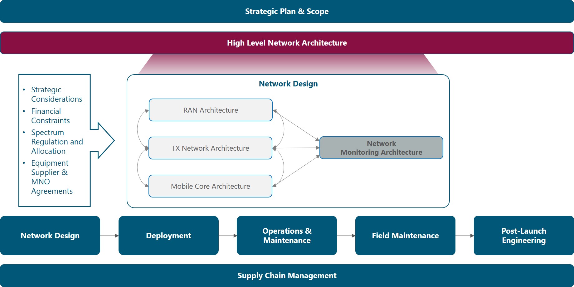
Figure 1. Module Framework
Figure 2 presents a functional view of the Network Monitoring Architecture module where the main functional components are exhibited as well as its main inputs and outputs. Each functional block is discussed in its own section of the outline, detailing the impact of the respective inputs. In addition, a final section regarding outputs is provided.
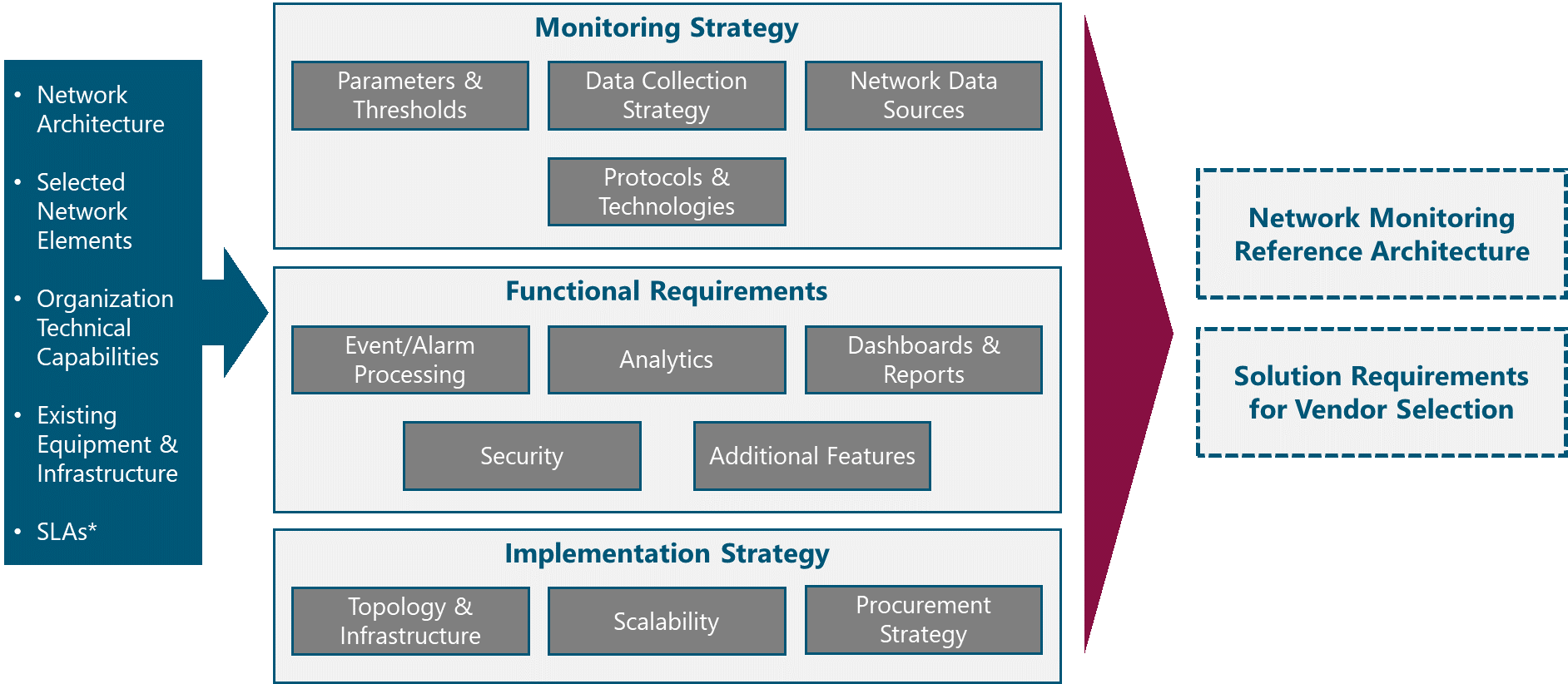
Figure 2. Network Monitoring Functional View
The rest of this module is structured as follows: Section 2 provides an analysis and guidance to define the aspects related to monitoring strategy including data sources and monitoring technologies. Section 3 covers the functional requirements for a network monitoring solution; and Section 4 discusses the various options to implement network monitoring in a NaaS Network. Finally, Section 5 discusses how to tie all components together into a formal Reference Architecture and Requirements Specification.
2 Monitoring Strategy Definition
Overview of strategic aspects of network monitoring, including parameters, data sources and monitoring technologies, providing the NaaS Operator with criteria and guidelines to define its own Monitoring Strategy.
2.1 Network Monitoring Fundamentals
Network Monitoring is the practice of continuously measuring, analyzing and reporting outages, faults, deficiencies and performance metrics regarding network elements, links and services, contributing to maintain and optimize network availability and performance.
The process of network monitoring is automated through network monitoring systems, usually implemented as software only, but in certain cases using additional hardware to improve visibility into specific performance metrics.
Network Monitoring systems track and log network parameters and when predetermined thresholds are crossed, alarms are triggered and notified to the Operations personnel to initiate fault management procedures. In addition, performance metrics are also analyzed to look for optimization opportunities and to provide planning inputs.
Performance of Telecom business is greatly determined by network performance. In consequence, to improve/maintain business performance, network performance needs to be maintained/improved, requiring an effective network monitoring solution as you can only manage what you measure. In this sense, network monitoring is an imperative for any communication service provider, fixed or mobile and of any size.
An effective network monitoring solution provides the following benefits:
In the NaaS scenario, network monitoring is even more critical:
In the following sections, the NaaS Operator is guided through the definition of the main aspects of network monitoring.
2.2 Parameters & Thresholds
The first step towards the definition of the Network Monitoring Architecture is to identify what to monitor. To do so, the NaaS Operator needs to have a clear definition of the key performance indicators (KPIs) for its network. Then, the most important parameters to be monitored and thresholds for alerts are selected.
KPIs measure network performance on a macro level, they are metrics of interest for the NaaS Operator management team. KPIs are used to communicate the overall status of the network, benchmark networks, detect problem areas and manage Service Level Agreements with customer Operators and with Service Providers (e.g. transport service providers).
KPIs are relevant to network operations as they allow to:
KPIs are calculated from network performance monitoring counters, alarms and status parameters, which are continuously collected by the Network Monitoring System. To achieve a well-monitored network, the following categories of KPIs shall be considered:
In addition, for RAN and E2E the following categories can be considered:
KPIs for each category and recommendations to set thresholds are provided in Table 1. In addition, the NaaS Operator is encouraged to use the KPI Specification Template to establish and document its own KPIs and thresholds.
|
Category |
KPI |
Description |
Recommendations |
|
Availability |
Monthly Availability |
Proportion of time that the service provided by the network is in working condition |
E2E Availability per site should be at least 99% which represents almost 4 days of downtime per year. Availability of network elements and network sections should be adjusted accordingly |
|
MTBF |
Mean time between failures. Period with continuous uptime averaged over a month or a year |
For information purposes only |
|
|
MTTR |
Mean time to repair. Period to repair a network failure averaged over a month or a year |
To be defined based on SLAs with customers |
|
|
Integrity & Performance |
Latency |
Round trip time. Average time for a packet to be sent, reach destination and get back to the sender |
The E2E Latency or round trip time should be below 80 ms. Latency for each segment of the network should be adjusted accordingly. Latency for satellite links will be significantly higher (at least 400 ms) |
|
Average Throughput |
Average transmission rate for a specific service or interface. Should be measured in both ways: downlink and uplink |
For RAN Equipment <50% of maximum eNodeB capacity. |
|
|
Max Throughput |
Maximum transmission rate for a specific service or interface within a time interval. Should be measured both ways: downlink and uplink |
For information purposes only |
|
|
Packet Loss Rate |
Percentage of the number of lost or errored packets between two interfaces over a specified time interval |
< 1% |
|
|
Load / Utilization |
Busy Hour Average Active Users |
Average number of users with active sessions at busy hours |
< 50% of eNodeB capacity |
|
Busy Hour Peak Active Users |
Peak number of active users at the busy hour |
< 80% of eNodeB capacity |
|
|
Traffic Volume |
Total amount of data (in MB or GB) that has been transmitted at the user, cell and network level |
For information and billing purposes. Can be calculated on a daily and monthly basis |
|
|
Utilization |
Percentage of resources being used at any point in time. Should consider cell, interface, CPU, and Memory utilization |
80% |
|
|
Accessibility |
E-RAB Establishment Success Rate |
Ratio of successful E-UTRAN Radio Access Bearer (E-RAB) establishment procedures with respect to the total number of E-RAB establishment attempts |
99% |
|
EPS Attach Success Rate |
Ratio of successful Evolved Packet System (EPS) attachment procedures with respect to the total number of attach requests |
5% |
|
|
Call Setup Success Rate |
Percentage of calls successfully established without facing blockage in the network as a ratio of the total number of call attempts |
98.50% |
|
|
Call Setup Time |
Average time to establish a voice call, from call initiation to the called party being alerted |
10 s |
|
|
Retainability |
E-RAB Drop Rate |
Ratio of abnormal E-RAB releases with respect to the total number of E-RAB successfully established |
2% |
|
Call Drop Rate |
Percentage of calls dropped due to technical problems or coverage gaps in the service providers network as a ratio of the total number of calls successfully established |
1.50% |
|
|
Call Success Rate |
Percentage of calls successfully established without facing blockage in the network as a ratio of the total number of call attempts made and then successfully terminated from the user-end |
97% |
Table 1. Baseline KPIs and Recommendations.
Once KPIs are established, the NaaS Operator must define which parameters should be monitored throughout the network to feed the calculation of the KPIs and to identify any performance issues or element failures.
Table 2 shows a baseline recommendation of parameters to be monitored in the NaaS network with comments for applicability and further customization.
|
Network Element |
Parameter |
Comments |
|
Generic |
Interface Status |
Physical interfaces at minimum. Logical interfaces may be monitored as well |
|
Traffic Counters |
Various granularities can be defined. Baseline is at the physical / logical interface level |
|
|
Interface Utilization |
For all interfaces |
|
|
Packet Errors |
Error counters for each interface/link |
|
|
Interface Rx Power |
Applies for Radio or Optical Interfaces |
|
|
CPU Utilization |
For all network elements |
|
|
Memory Utilization |
For all network elements |
|
|
Network Element (NE) Temperature |
For all network elements |
|
|
Power Status |
Whether the Primary, Secondary, and/or Batteries are working properly |
|
|
Fan Status |
Only for NEs with integrated fans |
|
|
RAN Equipment |
Throughput |
Average and Maximum, Downlink and Uplink |
|
Radiofrequency Resource Utilization |
Number of PRBs being used or percentage of PRBs being used in Downlink and Uplink |
|
|
Attached Users |
Number of registered users |
|
|
Active Users |
Number of users with an active session |
|
|
Radio Resource Control (RRC) Protocol Performance Counters |
Includes number of E-RAB requests, attach requests, call setup requests, successful and failure events |
|
|
Downlink Latency |
Processing latency at the eNodeB, from the time a packet is received at the Backhaul interface to the time the packet is scheduled in the air interface |
|
|
Transport Equipment |
Layer 2/ Layer 3 Protocol Status |
Refers to routing tables, neighbor status, convergence status, etc. |
|
Layer 2/ Layer 3 Protocol statistics |
Refers to statistics regarding number of events, number of neighbors, etc. |
|
|
Internet Control Message Protocol (ICMP) Statistics |
Ping statistics: number, RTT, packet loss |
|
|
Core |
Control Plane Performance Counters |
Counters for signaling events |
|
User Plane Performance Counters |
Traffic statistics at the user plane that may be useful for billing customer MNOs |
|
|
Power |
Mains Status |
AC Power received from the power company |
|
Battery Status |
Charging/Discharging, Voltage |
|
|
Input Voltage |
Input voltage to the power supply unit and rectifiers |
|
|
Output DC Voltage |
Output voltage delivered to network elements |
|
|
DC Load Current |
Current drained from the power supply unit to the network elements. |
Table 2. Baseline parameters to be monitored in a NaaS Network.
In addition, the following recommendations are provided to the NaaS Operator:
In order to customize monitoring parameters and thresholds for its own network, the NaaS Operator may use the Monitoring Parameters Definition Wizard.
2.3 Data Collection Strategy
In the previous section, recommendations to specify network parameters to be monitored have been provided. Now it is vital to consider that network monitoring data is continuously generated and important decisions regarding where and how often to collect this data must be made.
As the amount of monitored parameters and collection frequency increases, operational improvements follow an S-curve. As shown in Figure 3, a small amount of data with low frequency offers low value, then, there is an inflection point where incremental data can deliver high value; however, there is a second inflection point from which more data starts to have diminishing returns.
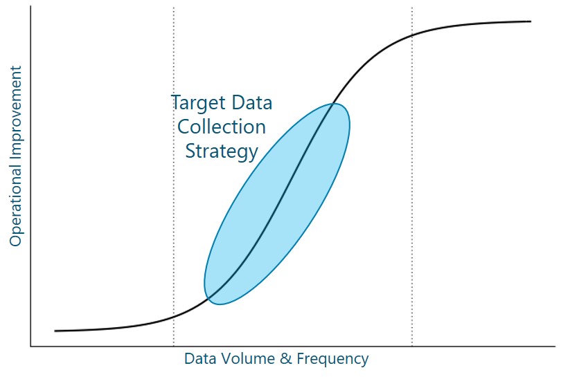
Figure 3. Operational Improvements and Data Collection Strategy.
Furthermore, it is important to consider that a higher amount of data and higher collection frequency means higher monitoring complexity and cost, and higher monitoring overhead on the network. Thus, the NaaS Operator should find an equilibrium point where the operational improvements are exploited under an adequate investment and complexity for the monitoring system.
The following recommendations are provided for the NaaS Operator to define its own monitoring intervals throughout the network:
2.4 Network Data Sources
Typically, monitoring data is obtained from network elements. However, in some cases an additional level of visibility or functionality requires additional hardware to monitor the network. Furthermore, virtualized functions and cloud services cannot be directly monitored; instead, APIs are used to monitor their performance and availability status.
Below, a description and comparison of the most common network data sources are presented. Afterwards, guidelines to select the most suitable data sources based on the NaaS Operator use cases, constraints and requirements are presented.
Table 3 summarizes and compares the network data sources described above.
|
Data Source |
Type of Data |
NE Impact |
NE Support |
|
NE – MIB/ Data Model |
Availability Status & Performance Counters |
Low |
Supported by virtually ALL network elements |
|
NE – Flow Data |
IP Flow Statistics |
Medium |
Supported by carrier grade routing and switching equipment |
|
NE – Mirror Port |
Packet |
High |
Mainly routing and switching equipment. A physical port may be required on the monitored network element |
|
TAP |
Packet |
None |
Not Required |
|
Probe & Synthetic Test |
Performance Measurements |
None |
Certain network elements, may support synthetic tests |
|
API |
Availability, Performance & Status |
None |
Not Required |
Table 3. Network Data Sources.
In order to select which data sources to implement for its Network Monitoring Architecture, the NaaS Operator can go through the process flow presented in Figure 4. Also, the Network Data Sources Selection Wizard can be used for the same purpose.
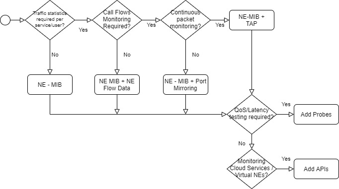
Figure 4. Network Data Sources Selection Process.
2.5 Monitoring Protocols & Technologies
In addition to data sources, various protocols and techniques exist to collect data from these sources. In the following sections, the main protocols and techniques are described, providing guidance for the NaaS Operator to determine which methods to implement based on the use cases and requirements for each of them.
2.5.1 SNMP (Polling)
Each network element has embedded agents that speak Simple Network Management Protocol (SNMP). These agents are interrogated with a polling-based approach, returning metrics from the network element.
Polling consumes many resources from the network monitoring system, especially as the number of monitored network elements increases. A problem with SNMP is that low latency updates coming from network elements may be delayed due to the polling mechanism
Use Case: SNMP covers the basic requirements for availability and status metrics, including slow traffic monitoring.
Requirements: SNMP is supported by virtually every possible network equipment and monitoring software. The only requirement to set it up is to perform an adequate configuration at the network element and monitoring system level.
A deeper exploration of SNMP features is given in the SNMP Primer.
2.5.2 NetFlow
NetFlow is a method used to report on the traffic that is passing through network elements. Rather than deploying probes around the environment to capture, analyze, and report on traffic behaviors, flows are collected and processed by collectors. The utilization of collectors allows to apply analysis technologies to provide insight into which devices and applications are consuming bandwidth, how long the conversations are lasting and who is participating in them.
Because the data is summarized (and sometimes sampled), a degree of detail is removed to reduce bandwidth overhead, simplify processing and to extract meaning from the actual network data.
Several protocols, both proprietary and standard-based that operate under this principle have been defined. Proprietary protocols include among others NetFlow from Cisco, J-Flow from Juniper and NetStream from Huawei. On the other side, standard-based protocols include sFlow which is considered an Industry Standard and IPFIX that has been specified by the IETF.
Use Case: Detailed traffic analysis where it is not required to analyze a specific set of network packets, nor does it require timing or delay information. Basically, NetFlow enables network planning and optimization with the right granularity to keep the system simple and with reasonable storage requirements.
Requirements: To leverage NetFlow technologies for network monitoring, the NaaS Operator needs to make sure whether network elements support it and under which protocol. In addition, hardware or software-based collectors are required as well as some form of pre-processing and long-term storage.
For a detailed description and comparison of NetFlow and Packet technologies, the NaaS Operator may consult the Primer on NetFlow and Packet Data.
2.5.3 Packet Collection
Packet collection consists of retrieving an exact copy or relevant data from every packet transmitted over a network interface. Packets offer full visibility into bursty traffic behavior, enabling a greater insight and precision than other technologies. Packets provide information about the precise microsecond when a packet passes a capture point, allowing to measure response time and network latency.
Packet collection is enabled through the potentially costly (and often, impossibly costly) implementation of hardware collectors to capture packets.
Use Case: Detect and troubleshoot performance problems that are beyond network congestion and that are timing-based such as excessive delays, latencies, etc. Usually applied only to critical interfaces such as mobile core interfaces to validate protocol signaling and procedures.
Requirements: A capture point (TAP) and capture device (collector) must be deployed to get packet visibility on specific interfaces to be monitored. As the network grows, more TAPs and collectors are required. When signaling traffic is encrypted, an additional burden is put into the collectors that must perform decryption of this traffic, implying additional processing capacity and costs. High storage requirements are also characteristic as information about each packet is stored for analysis.
The NaaS Operator is encouraged to read the Primer on NetFlow and Packet Data for further comparison of these technologies.
2.5.4 Streaming Telemetry
Similar to SNMP, with Streaming Telemetry, availability and performance data is collected from the network elements, but instead of using the polling mechanism, it uses a pushing mechanism to overcome the inefficiencies of polling. Under this pushing mechanism, the monitoring system subscribes itself to certain updates that each network element issues (streams) periodically or on an event basis.
By using the push mechanism, Streaming Telemetry enables a high reporting frequency (up to 10 s) for critical data and offers complete access to operational and configuration data using open data models. In addition, all parameters reported are time-stamped, allowing for a better understanding and analysis of performance metrics.
Streaming Telemetry can use various protocols for telemetry transport such as UDP, TCP and gRPC, which is a web-based protocol that significantly reduces the required bandwidth to transport data and adds TLS encryption of telemetry data.
Use Case: Streaming Telemetry is suited to any SNMP use cases and, in some cases, may replace NetFlow. However, the core use case is when low latency updates are required. In addition, it is used to retrieve configuration data and to interface with APIs that offer telemetry subscription services for cloud and virtualized network elements.
Requirements: The basic requirement is that the network elements or services must support the push mechanism and a suitable transport protocol. In addition, network elements should provide their data models in a standard format, being the YANG model the prevalent choice in the Industry. The Monitoring system architecture remains almost the same as with SNMP.
Further exploration of the principles, features, and benefits of this technology is provided in the Streaming Telemetry Primer.
2.5.5 Selecting Monitoring Protocols & Technologies
Based on the above descriptions, the NaaS Operator must define which monitoring protocols and technologies will be part of its Network Monitoring Architecture. The following recommendations are provided as a supporting guide for the NaaS Operator analysis:
As a complement to these guidelines, the NaaS Operator can make use of the Monitoring Technology & Protocol Selection Wizard.
3 Functional Requirements Specification
This section consists of a walk-through to explain functional aspects of network monitoring solutions and guidance to specify baseline requirements before the NaaS Operator engages in discussions with potential solution providers.
Furthermore, a Functional Requirements Template is provided to the NaaS Operator for customization, including a set of generic requirements that can be further complemented and edited according to each NaaS Operator network architecture and strategy.
3.1 Events & Alarms Processing
An event is something that happens in the network and has some importance or impact on the overall availability, performance or status. Most events are asynchronous due to changes in the state of network elements, links or user requests.
An alarm is a type of event, which is either generated automatically by network elements or by the network monitoring system based on performance thresholds.
In effect, one of the fundamental requirements for a Network Monitoring Solution is the ability to monitor events and alarms, and generate alerts for network elements, links and services. Events and alarms are monitored through syslog or SNMP traps, which are alert messages sent from a network element towards the network monitoring system. Furthermore, having continuous performance monitoring enables the generation of alerts based on performance levels, which is a vital tool to detect potential issues before they reach critical levels that ultimately disrupt network services.
As an alternative to SNMP or syslog, when using streaming telemetry, events and alarms based on performance can be configured at the network element to notify the monitoring system when they occur.
The NaaS Operator shall define events and alarms processing requirements for the Network Monitoring system. Minimum requirements are listed below and included in the Functional Requirements Template for customization:
- The System shall perform continuous real-time monitoring of network alarms using monitoring protocols and technologies defined by the NaaS Operator
- Vendor and network technology agnostic. The System shall support the monitoring of network elements (and cloud services) for any network technology (RAN, Transport, Cloud) and any vendor that supports the defined collection mechanisms.
- Alarm reporting. The System shall process and report, at minimum, the following types of alarms:
- Interface and Port failures
- Power source loss / power source switch
- Synchrony alarms
- CPU/Memory Overload
- Service outages
- Temperature
- External Alarms connected to network elements
- Threshold configuration. The System shall allow configuration of performance thresholds for alarm generation
- Alert prioritization. The System shall allow configuration of alarm criticality and prioritization of alerts.
- Alarm correlation and deduplication. The System shall identify interdependencies of alarms generated from an initial alarm, consolidating alarms that are duplicated.
- Alarm filtering. The System shall allow the operator to filter alarms for visualization according to several criteria. At a minimum, filtering by network element, geography and criticality.
- Alarm Disabling. The System shall consider an option to manually clear or disable alarms to minimize alerts during maintenance works or changes in the network.
- Automated Alarm Clearing. The System shall clear all alarms once the network condition returns to the normal state.
- Alarm notification (alerting). The System shall generate notifications to specific personnel or other systems (such as Ticketing Systems) through various channels such as SMS, email, messaging apps and API notifications.
- Alarm Log. The System shall keep a log of all the alarms presented in the network.
3.2 Analytics
Network analytics is the practice of using different types of network data to identify trends and patterns, and using statistical techniques to improve the performance, reliability, or security of the network as well as to find out solutions for critical problems.
Network analytics provide network operators in general and NaaS Operators in particular, with deep insights of their networks, enabling them to make better decisions for troubleshooting, threat remediation decisions, business planning and performance optimization.
Other benefits of an efficient implementation of network analytics in the network monitoring system are network scalability, reduced operational costs and resource optimization:
A fundamental aspect of analytics is to baseline network behavior over a couple of weeks or months. Knowledge of baseline behavior aids proactive troubleshooting and provides essential input for advanced analytics algorithms.
Network Analytics can be classified in various ways. For simplicity, only two classifications are presented here. The first classification divides analytics into Real-Time and Batch or Historical Analytics. Real-time analytics uses real time data to enable quick detection of network and service degradation as well as continuous network status reporting. On the other hand, Batch Analytics allows for powerful analysis for diagnostics and optimization that is done offline using historical data.
The second classification is based on the function performed by the analytics. As shown in Figure 5, there are Descriptive, Diagnostic, Predictive and Prescriptive Analytics and each of them answers a different question.
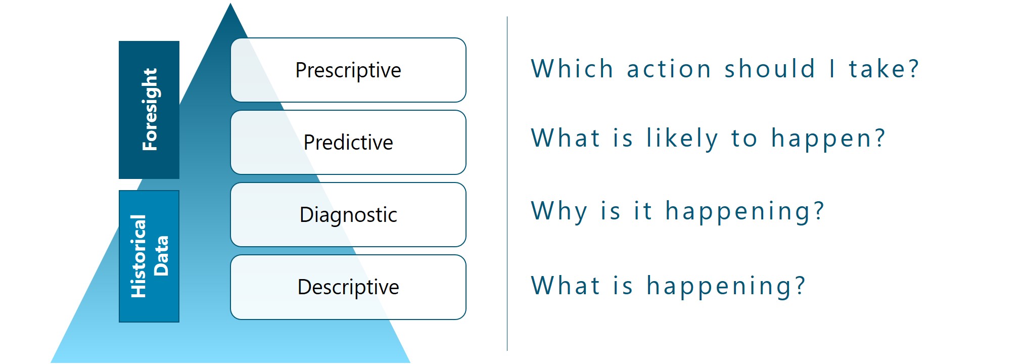
Figure 5. Network Analytics Categories.
In todays market offering, there are several monitoring solutions that incorporate Artificial Intelligence and Machine Learning into their analytics products. Thus, it is important to have a good understanding of what this means. Machine learning is a subset of artificial intelligence, and it gives analytics engines the ability to automatically learn and improve from experience without being explicitly programmed.
Machine learning offers significant increases in the accuracy of insights and remediation because the decision trees are modified to meet the specific conditions of a network’s configuration, its installed hardware and software, and its services and applications.
However, the NaaS Operator should be aware that Analytics are as good as the data that is fed to these tools. Thus, analytics should be appropriate to the network monitoring strategy. It is not recommended to have full Machine Learning Prescriptive Analytics if the monitoring of the network is going to be using SNMP and 15-minute reporting intervals.
In many NaaS scenarios, simple analytics have the potential to provide huge value for NaaS Operators at a reasonable cost. In consequence, the NaaS Operator shall define adequate analytics requirements for its Network Monitoring system. Minimum requirements are listed below and included in the Functional Requirements Template for customization:
- Baselining. The System shall have the capability to establish a baseline behavior of the network, notifying the Operator deviations from it and allowing to establish alarm thresholds.
- Real-Time & Batch Analytics. The System shall provide real-time and batch analytics, each with different processing software or mechanisms, supporting real-time alerts and performance reporting, as well as historical performance analysis
- Descriptive Analytics. The System shall support descriptive analytics that proactively detects network and subscriber performance degradation, anomalies and congestion and allow for calculation of the KPIs specified by the NaaS Operator.
- Trending Analysis. The System shall provide trending features, allowing to identify potential performance degradations or security threats, detect potentially damaging conditions, including those that only occur during peak traffic conditions.
- Diagnostics. The System shall provide the diagnostic workflows and forensic data to identify the root causes of performance degradations or failures
Additional requirements that may be considered by the NaaS Operator, based on the size and maturity of the network, monitoring strategy and financial constraints are:
- Predictive Analytics. The System may incorporate machine learning algorithms for performance forecasting and fault prevention.
- Prescriptive Analytics. The System may provide prescriptive capabilities that allow the network to evolve from reactive detection to preventive automatic actuation in advance of network problems.
- Advanced Performance Analysis. The System may support detailed analysis of service and network performance to enable Quality of Experience estimation and to analyze LTE radio and signaling events, identifying potential issues with specific cells, users, applications and devices.
3.3 Dashboards & Reports
As stated before, you only manage, what you measure. However, once measuring is taking place, the next critical issue is to visualize. Data becomes useful only when it is presented clearly to the right audience that can be Operations personnel, Engineering personnel or Managers.
A network dashboard is a panel that provides an at-a-glance overview of the current status of the network, with KPIs and critical parameters from cell sites, microwave radios, satellite links, routers, switches, core entities, services and underlying infrastructure. A dashboard allows to see the big picture of the network and provides the ability to drill-down for specifics on quasi-real-time. Figure 6 shows an example of a network monitoring dashboard.
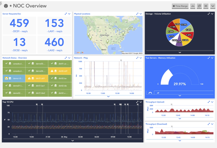
Figure 6. Network Monitoring Dashboard
On the other side, reporting is key to keep stakeholders aware and informed about the status and behavior of the network over a period of time, using historical data. Apart from the internal evaluation of the network, reporting might be required for SLA and regulatory compliance, and for customer billing.
Reporting is a task that is performed periodically or on-demand in every network. Thus, it should be automated to ensure that resources devote time to other high value-activities.
The NaaS Operator shall define Dashboarding & Reporting requirements for the Network Monitoring system. Minimum requirements are listed below and included in the Functional Requirements Template for customization:
- Network Visualization. The System shall provide configurable views of the network, considering at least a Geographic and topology view.
- KPI Visualization. The System shall be able to show the selected KPIs on a list, chart or map.
- Top Offenders. The System shall identify and show elements considered as top offenders under specific KPIs defined by the NaaS Operator.
- Deep Dive Analysis. From the dashboard view, the System shall allow deep-diving into a region, network technology, site, network element or interface.
- Alarms & Notifications. The System shall generate visible notifications of alarms through text and changing the color of icons in the dashboard depending on the criticality.
- Dashboard customization. Dashboards shall be configurable for various levels and roles, allowing to show different network views, KPIs, charts, etc.
- Report Generation. The System shall provide reporting capabilities, allowing to configure metrics to be reported, including KPIs, individual element parameters applying averages, distributions historical series and other operations.
- Reporting Granularity: Report granularity shall be customizable, including reports at the network, region, network segment, technology and network element level.
- Report Periodicity. The system shall support on-demand or periodic generation of reports, with configurable periodicity including at least daily, weekly, monthly and yearly options.
- Data Export. The System shall allow to export any monitoring data as files in machine-readable formats or through a web API.
3.4 Security
Security is a vital aspect in every network and system as attacks can disrupt the network and end user services, potentially impacting the privacy of the Organization, Customers and End Users.
In the case of the Network Monitoring system, security has to be addressed in two ways: Security in the connection to Network Elements and network data collection; and security and integrity of the Monitoring System itself.
In the following, the minimum set of security requirements that the NaaS Operator should specify for the Network Monitoring System is presented. These requirements are also included in the Functional Requirements Template, which can be customized by the NaaS Operator.
- Access Control Lists. Access to the network elements for monitoring shall be controlled through access control lists.
- Secure Protocols. Data collection from network elements shall be performed using secure protocols. If using SNMP, it shall be SNMPv2 at minimum, using SNMPv3 as a preferred option.
- System Access. Access to Network Monitoring System shall be allowed only from internal network segments or through VPN.
- User Authentication. Users shall access the System using Diameter, Radius or local authentication, with individual username and password.
- User Management. The system shall provide user management capabilities such as creation, modification and deletion of users.
- Security Logs. The System shall keep a security log, tracking all security events, including failed access attempts.
Additional security requirements should be considered, as appropriate by the NaaS Operator, complying with any regulatory or customer requirements.
3.5 Additional Features
Up to this point, major requirements for the Network Monitoring System have been analyzed and specified. However, some additional features could be integrated and may be of value for some NaaS Operators.
Some of these requirements are enumerated below for the consideration and evaluation of the NaaS Operators. As previous requirements, they are part of the Functional Requirements Template:
- Network Auto-discovery. The System may integrate auto-discovery functionalities to automatically scan the network and add network elements for inventory and monitoring.
- Business Level Analytics. The System may provide in addition to network analytics, business-level analytics.
- Integration with automated workflows. The System may allow for integration with automated workflows for ticket generation and network automation.
- Quality of Experience. The System may support Quality of Experience analysis features.
- Protocol & Call Flow Analysis. The System may provide protocol and call flow analysis capabilities in order to detect signaling issues and anomalies in E2E procedures. (Requires packet data capture)
- Analysis of log data. The System may support monitoring and analysis of log data from network elements.
4 Implementation Strategy Definition
This Section presents a high-level analysis of implementation options for network monitoring solutions, providing instructions to the NaaS Operator to define its own implementation strategy.
4.1 Topology & Infrastructure
Network Monitoring solutions are integrated by several functional components, as shown in Figure 7. The actual configuration may differ between solutions, but in general, most solutions will preserve the components shown in the Figure.
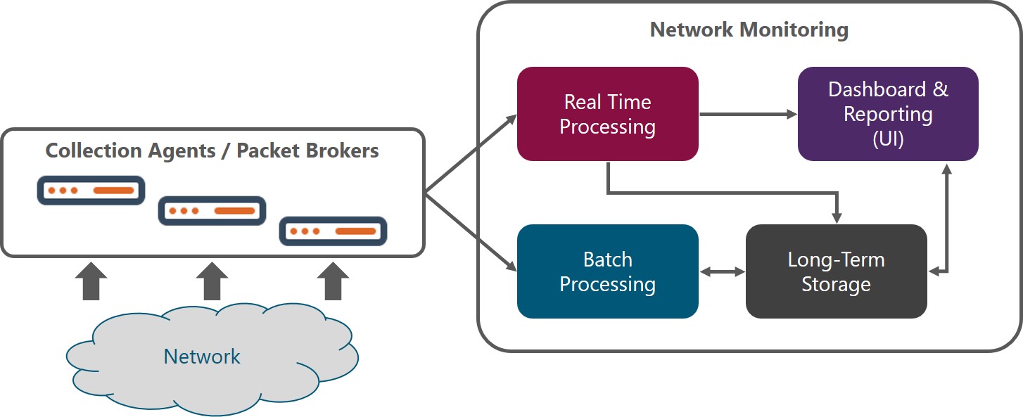
Figure 7. Network Monitoring Functional Architecture
When evaluating solutions, NaaS Operators should look for these functional components or equivalent, as every vendor or open source project may assign a different name to the specific components of the solution, but functionality should be the same.
Components of network monitoring solutions are usually implemented as software and this should be the preferred option for NaaS Operators as it offers high flexibility and scalability, even if there are some commercial solutions implemented in hardware.
It is important to consider that for certain cases hardware may be a requirement. For example, probes are mainly tied to specific hardware, and when collecting packet data, collectors are most of the time a hardware appliance.
4.1.1 Topology
Topology refers to location and interfaces between network monitoring components. At a high level, 3 models can be specified:
Table 4 below shows a comparison of these topologies that aims to support the NaaS Operator to define the topology for its own solution.
|
Criteria |
Centralized |
Distributed |
Hierarchical |
|
Reliability |
Single point of failure |
Better reliability without a single point of failure. Natural geographic redundancy |
Highly reliable. Allows for local and centralized monitoring without a single point of failure |
|
Scalability |
Constrained by bandwidth |
Scales seamlessly with the network, just by adding a new monitoring instance |
Scales locally. The problem of bandwidth can be solved by filtering data that goes directly to centralized monitoring. |
|
Complexity |
Easiest to deploy and maintain |
Easy to deploy but maintenance requires personnel in various regions |
The Integration of distributed and centralized instances can get complex. |
|
Cost |
Low |
Medium (depends on the number of regions/instances) |
High. Basically, it is basically the sum of centralized and distributed |
Table 4. Network Monitoring Topology Comparison
NaaS Operator shall consider the criteria above to select an adequate topology. As a general rule, the centralized topology is recommended for most cases. However, there are certain cases in which a hierarchical topology may suit better the NaaS network; these cases are when the NaaS Operator has multiple teams and facilities distributed in various regions and/or when collecting NetFlow and packet data.
A special case of the hierarchical topology is that in which the network monitoring is collecting data from vendors NMS or OSS and not directly from network elements.
It is recommended to implement a monitoring strategy with High-Availability through failover. This characteristic is achieved through redundancy in the network monitoring solution components. The NaaS Operator should consider at least redundancy for power supply, servers and network connectivity.
4.1.2 Network Monitoring Connectivity
Connectivity from the Network Monitoring system towards the network can be achieved with an in-band or out-of-band scheme. The in-band scheme consists of using the network that is being monitored to transport its own monitoring data. On the other side, out-of-band connectivity consists of deploying a secondary network just with monitoring purposes. This is required for most solutions that collect packet data.
For the rural environment of NaaS Operators is highly (and in most cases prohibitive) costly to deploy an overlay network in addition to the RAN and transport network that provides the network services. Thus, the NaaS Operator shall define in-band connectivity for network monitoring. Out-of-band connectivity can be defined only in very specific cases and locations such as transport or core nodes with existing network infrastructure where packet data is being monitored.
4.1.3 Cloud vs On-Premise
For many years and in many networks, network monitoring solutions have been deployed on-premise. However, there is a trend towards cloud-based network monitoring due to lower CapEx investment and fast deployment.
Todays commercial solutions are divided between on-premise and cloud deployment, with some of them offering both options.
The NaaS Operator should evaluate solutions with these two implementation approaches and select the approach that fits better its requirements and constraints. To that extent, Table 5 below makes a comparison between both approaches that can support the NaaS Operator to make the right decision.
|
Criteria |
On-Premise |
Cloud |
|
Install & Setup |
Installation and setup of on-premise software imply significant effort and time. |
Instant setup, complete and pre-configured for rapid deployment with low risk. Devices need to have access to the Internet, which requires an active and secure connection for the whole network. |
|
Scalability |
Scaling requires new hardware and infrastructure/connectivity expansion |
Highly granular and timely scaling. Expansion of connectivity to the cloud might be required. |
|
Reliability |
Owned facilities will have lower reliability than the cloud. However, depending on cloud connectivity the on-prem solution may have better reliability |
Highly reliable. A weak point could be connectivity to the cloud. |
|
Cost |
Most vendors require the purchase of a perpetual software license; however, some vendors offer subscription models similar to cloud solutions and some open source solutions are license free |
Low TCO due to avoidance of upfront costs (hardware, installation, setup) and pay-as-you-grow schemes |
|
Security |
High level of data security when set up correctly |
Medium to High level of security given that devices are connected to the Internet. It requires diligence to adequately secure the network. |
Table 5. On-Premise vs Cloud Comparison.
As a rule of thumb, NaaS Operators with small networks and tight financial constraints may decide for on-premise open source monitoring systems. If not in this case, the Operator should prefer cloud solutions due to setup, maintenance and cost efficiency. Nevertheless, other factors may influence the decision and should be taken into account by the NaaS Operator, such as regulatory constraints, cloud connectivity issues and the pre-existence of on-premise solutions and skills to set up and maintain them within the Organization.
4.1.4 Interfaces to Other Systems
The Network Monitoring System is not isolated in the NaaS environment. Thus, it requires connectivity to and from other systems, such as OSS/BSS, Network Management Systems, Cloud Services, virtualized elements and cloud management platforms.
The connectivity to these systems is increasingly done through web APIs and data models, and the NaaS Operator should specify the support of these interfaces to consume and provide data from/to other systems.
In addition, SNMP interfaces shall be considered as many systems still use this protocol for management connectivity.
Based on the analysis in the sections above, the following recommendations are provided to the NaaS Operator for the definition of Topology & Infrastructure aspects of the Network Monitoring Implementation Strategy:
4.2 Scalability
Implementation of the Network Monitoring System must consider scalability requirements to ensure that it will support current and future load in terms of data collection, processing and storage.
The NaaS Operator may use the following guidelines to define scalability requirements:
4.3 Procurement Strategy
Acquisition and implementation of the Network Monitoring System can be done in various ways, depending on the size of the organization, skills and financial constraints. At a high-level three aspects must be considered by the NaaS Operator
- Open source vs Proprietary Software
- Insource vs Outsource implementation
- Single vendor vs Best-in-breed
These aspects are discussed in the following sections.
4.3.1 Opensource vs Proprietary Software
Opensource refers to free or low-cost software that allows to see and customize its code. The developer community is responsible for the performance and improvement of the tool. The NaaS Operator may customize and improve the code to meet its needs, which may require significant time and effort depending on the level of customization desired.
Support for opensource solutions is offered through forums and articles. For certain tools, there exist robust communities that provide all the required support.
Regarding cost, many opensource platforms provide the code free of charge, however, there are times when an opensource monitoring solution requires users to pay for extra features and added functionalities.
On the other hand, proprietary software will have a cost, with varying pricing schemes which can be based on the number of network elements, bandwidth, storage capacity or a one-time fee. In this case, performance is ensured by the vendor, which offers proven functionality that is constantly improved, and it generally includes the option to contact tech support agents.
The main drawback (apart from cost) for proprietary software is the lack of customization. Even if the tool allows for customization of dashboards, reports, etc. it is tied to the existing code. Specific features required by the NaaS Operator may never see the light of the day as the tool follows each vendors roadmap. In this case, its important that if choosing proprietary software, the NaaS Operator makes sure that the tool has all the required functionalities.
The final decision depends on how the NaaS Operator weights each criterion. If cost or flexibility is the main driver, the best option is opensource. However, if performance is critical and there is an important need for support, the NaaS Operator should select proprietary software.
In addition, when choosing opensource software, the NaaS Operator must check any relevant legal issues and compliance requirements to make sure the software can be used for commercial use.
The NaaS Operator can get started taking a look at the Monitoring Tools in the Tool Catalogue provided.
4.3.2 In-source vs 3rd Party Implementation
This aspect refers to the resources that will ultimately implement the solution: personnel from the NaaS Operator or a 3rd Party company which can be either the software vendor or a system integrator.
For the NaaS Operator this should be a matter of weighting availability and skills of the internal resources vs required timelines for the implementation. If these resources are not available or they do not have the required skills and expertise to guarantee an effective and efficient implementation, then the NaaS Operator should prefer a 3rd Party Implementation.
4.3.3 Single vendor vs Best-in-Breed
Finally, the NaaS Operator should define whether it prefers to implement the complete Network Monitoring System through a single vendor or to apply a best-in-breed approach. The best-in-breed approach allows to select the best option for each functional block of the solution: hardware/cloud provider, collection agents, storage, processing and dashboards.
The best-in-breed applies mainly to opensource implementations, but it can also be applied to proprietary software, where the NaaS Operator or a System Integrator integrates a solution through components from various vendors.
The recommendation is for NaaS Operators that are just getting started to go with a single vendor or single opensource project. Then as the network matures or if the NaaS Operator has previous expertise, start incorporating various vendors or opensource projects.
5 Network Monitoring: Reference Architecture & Requirements Specification
After going through the previous sections, the NaaS Operator has been enabled to establish its monitoring strategy, specify functional requirements for the network monitoring solution and define the implementation strategy.
Now, the NaaS Operator is encouraged to follow the procedure below and use the provided Network Monitoring Architecture Template in order to document these decisions and communicate requirements to the overall NaaS Organization and potential vendors.