
Network as a Service (NaaS) PlayBook
1. Cell Site Maintenance Introduction
Cell Site Maintenance refers to the functional checks, servicing, repairing or replacing the necessary equipment and building infrastructure at the Cell Sites. Regular equipment maintenance ensures that each device operates efficiently during its intended life span. Therefore, maintenance is a time-based or equipment-based function, which can be categorized in Preventive or Corrective Maintenance. A balance between preventive and corrective maintenance in cell sites is required to keep the quality and service continuity of NaaS Operators Radio Access Networks.
Preventive maintenance refers to the functional checks and services performed on a time-based schedule. It is based on the premise that an important number of equipment failures or malfunctions can be prevented if a comprehensive maintenance schedule is followed. Preventive Maintenance is performed regularly on the fans, seals, cables, connections, batteries as well as on the supporting infrastructure of the cell sites such as towers, shelters, mounting ancillaries and fences. While preventive actions are performed to maintain the operative status of the network and maintain the condition of cell site facilities, unexpected events may occur.
Corrective maintenance refers to the actions that are performed to restore a failed piece of equipment to bring it back to a workable condition. It is typically performed when the equipment needs to be replaced. Corrective Maintenance is performed as well to repair the overall damage of the facilities which may happen due to unexpected events such as natural disasters or robbery.
This Module provides the NaaS Operator with recommendations and best practices for preventive and corrective maintenance at their sites, guiding NaaS Operators to prepare their reports that will evidence each maintenance intervention ensuring an overall good condition of their cell sites.
The main deliverables that the NaaS Operator will be able to generate through the use of this module are Preventive Maintenance Checklists and Reporting templates, which are basic documents that indicate the activities to be performed on the site and define standards to evidence their maintenance interventions.
1.1 Module Objectives
This module will introduce to the NaaS Operator the process and best practices to perform preventive and corrective maintenance of Cell sites as required by the NOC and/or Field Force Management.
The specific objectives of this module are to:
1.2 Module Framework
NaaS PlayBooks Framework shown in Figure 1 displays the PlayBook modules and their relationship to the Cell Site Maintenance Module.
After the Deployment Stream, the Operations & Maintenance module provides the necessary guidelines to establish the operational processes, which in turn, have a direct impact and influence on many aspects of the Field Maintenance Stream.
The Cell Site Maintenance Module is included within the Field Maintenance stream. It takes inputs from the Field Force Management, and Network Operation Center on the Operation & Maintenance Stream.

Figure 1. PlayBook Framework.
Figure 2 presents the Cell Site Maintenance functional view where the main functional content of the module is exhibited.
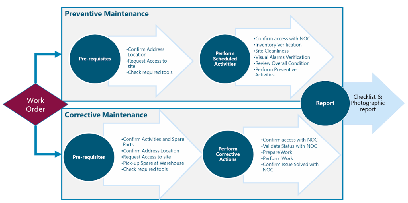
Figure 2. Cell Site Maintenance
The rest of the module is divided into two sections. Section 2 contains a high-level view of the Cell Site Maintenance Process, its prerequisites, and relations with the Field Force Management and NOC operations. Section 3 contains a high-level description of the key tasks to be performed as part of the preventive and corrective maintenance on the cell site, including the implementation guidelines to elaborate Maintenance Manuals and Maintenance Reports.
2 Cell Site Maintenance Process
Cell Site Maintenance comprises the set of activities performed by Field Technicians, coordinated by the Dispatch & Coordination function, as indicated in the Field Force Management Module. The objective is to perform the required tasks to prevent or correct malfunctions at the Cell Sites. This section contains the procedures and best practices to be performed during Cell Site Maintenance by Field Technicians.
2.1 Cell Site Maintenance Process Overview
A Maintenance intervention is triggered by a work order provided by the Dispatch & Coordination Function within the Field Maintenance team. A work order is a document that provides all the information about a maintenance task and outlines a process for completing that task. Work orders can include details on who authorized the job, the scope, who its assigned to, and what is expected from it.
Maintenance Interventions can be Preventive or Corrective. Preventive Maintenance is scheduled by Field Work Management following the engineering recommendations of the equipment vendor or NaaS Operator strategy as indicated in the Field Force Management module.
Corrective Tasks are triggered when the NOC detects a fault in a Cell site, or during Preventive Maintenance activities. In this latter case, Field technicians detect that Corrective actions are required, notifying Dispatcher/Field Management to schedule the required Corrective Intervention.
In both cases, a Maintenance report must be generated by the Field Technician after any Cell Site Intervention and must be stored to keep a Maintenance record.
This process is illustrated in Figure 3.
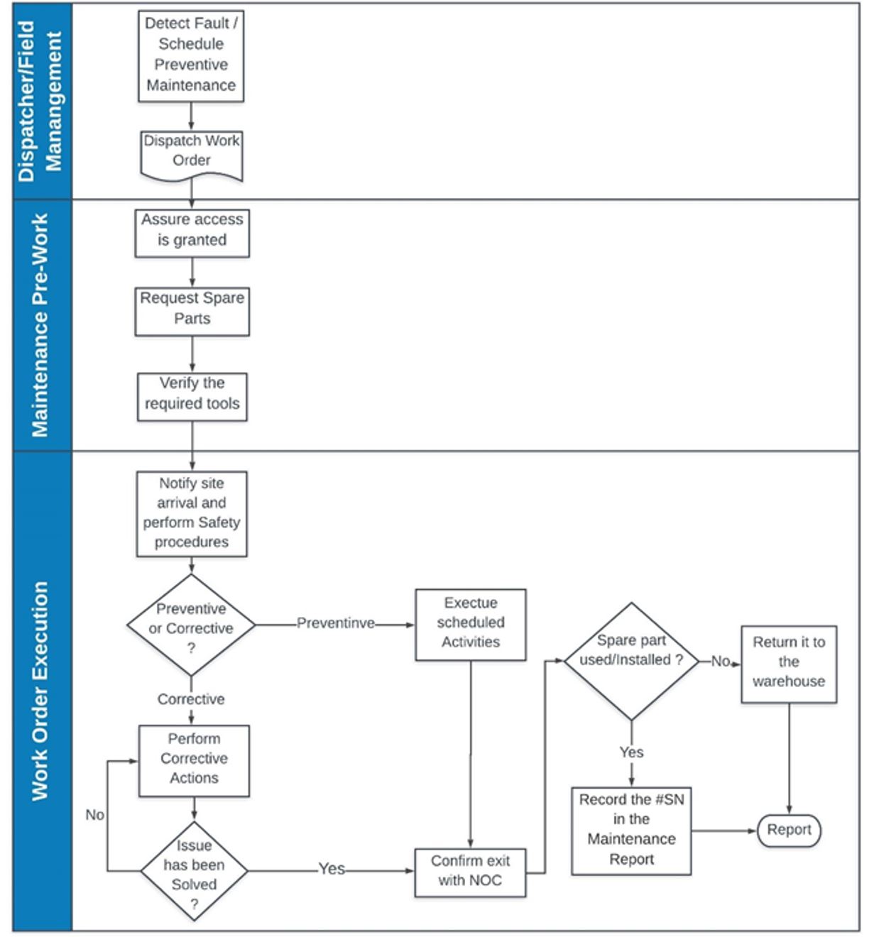
Figure 3 Cell Maintenance Process
In order to guarantee a successful Maintenance Intervention, Field Technicians must perform a set of tasks before each maintenance intervention, the following subsections contain the best practices to prepare the Field Maintenance Interventions.
2.2 Preparation for the Field Intervention
Depending on the complexity of the Work Order, the Field Manager or dispatcher should evaluate how many Technicians are required to attend the Work Order and request access to the site for all Field Technicians that will perform the interventions.
Once the Work Order is dispatched and access to the cell site has been approved, Field technicians must request the spare parts, ancillaries and other miscellaneous materials required for the task. This request is triggered directly by Field Technicians with support from the Network Operation Center. The Spare parts must include a list of the Ancillaries that will be required to replace the equipment (as indicated in vendor documentation), this will ensure that Field Technicians have everything to perform their maintenance intervention.
The Preparation of the maintenance intervention is of paramount importance since will enable Field technicians to perform the maintenance interventions at the expected time, avoiding delays during reworks, below are listed some consideration to prepare the maintenance interventions:
2.3 Work Order Execution
Execution of the work order should follow a set of tasks to diminish the risks involved in performing a Maintenance intervention. A Work order execution procedure ensures that the maintenance is performed properly, protecting Field Technician of possible injuries and prevents possible damage to the equipment. Below are listed the recommended tasks to execute a work order:
The following section details the Maintenance Guidelines which instruct NaaS Operators to implement the Maintenance Process for their Cell sites.
3 Maintenance Guidelines
This section provides a descriptive overview of the tasks involved in Maintenance Procedures, including Preventive and Corrective interventions and recommended actions for each case. Additionally, this section includes implementation guidelines that NaaS Operators may consider to elaborate their maintenance manuals to standardize their maintenance interventions.
3.1 Maintenance tasks description
In order to guarantee a successful maintenance operation, Field Technicians must perform a set of tasks before, during and after each maintenance intervention. This section describes the required tasks to be performed during the Preventive and Corrective Interventions.
3.1.1 Preventive Maintenance.
Preventive Maintenance consists of inspections and services that are carried out after a fixed time interval. The time cycle can be derived from the NaaS operator experience and from the manufacturer recommendation, which are justified by known aging behavior as well as statistics. For additional details about the preventive time cycle please see the Field Work Management module.
Preventive Maintenance activities include two subtasks: Inspection and depending on the situation either service or repair. Inspection refers to the measures taken to identify and assess the current condition of a maintenance object using a reference standard that must be met. Service or repair is defined as a non-invasive action that would not interrupt the network operation and is required to keep the good condition of the Cell Site. If Field Technicians note that in order to perform a repair is required to interrupt the network operation, they must notify the NOC / Field Management to evaluate and schedule the required corrective actions.
The following subsections contain a General Description of the Preventive Maintenance tasks for each element on a Cell site, categorized in Antenna System, Baseband/Transmission Equipment and Cabinet, Power System and Facilities & Shelter Environment.
3.1.1.1 Antenna System Preventive Maintenance
The Antenna System consists of Radio Units, RF Antennas and, if the site uses Microwave transmission, it will also include the ODU. Naas Operators may consider the tasks described in Table 1 to perform the Preventive Maintenance of an Antenna System. The Service is only executed if the item does not comply with the reference standard.
|
Item |
Condition Assessment |
Reference Standard |
Service Required |
|
Radio Units Isolation Caps |
Check whether the seals are damaged or loose |
The seals are tight and in good conditions, there is no presence of water within the seal. |
Replace the seals. |
|
Radio Unit Ports |
Check the insulation tape in the antenna and the radio ports. Check the Isolation to the Power Port and Fibers |
The insulation is in good condition; there is no presence of water in the seals. |
Replace the seals or insulation tape |
|
Radio unit and Antenna Mounting |
Check whether there are loose screws in the Radio Unit and Antenna Mounting Kit |
Radio Units and Antenna are properly fixed with no loose screws or bolts |
Tight the screws at the right torque |
|
Antenna Mechanical Tilt and Azimuth |
Check whether the Antenna Mechanical Tilt and Azimuth match with the corresponding values in the Site Documentation |
The Antenna Mechanical Tilt and Azimuth match with the corresponding values. |
Adjust the Mechanical Tilt and Azimuth following the maintenance guidelines of the Antenna Vendor. |
|
Microwave Dish |
Check the isolation of Intermediate Frequency cable or Ethernet cable and power cable as appropriate. Check the fixing screws of the mounting kit are tight with the right torque |
The connection is isolated with no presence of water and the dish is properly fixed with no loose screw tightened at the right torque. |
Tight the screws at the right torque, Replace the seals or insulation tape.
|
Table 1 Antenna System Preventive Maintenance
3.1.1.2 Baseband/Transmission Equipment and Cabinet Preventive Maintenance
The baseband, transmission and cabinets have maintenance items that should be checked periodically in order to extend their operational life. Naas Operators may consider the tasks described in Table 2 to perform the Preventive Maintenance on the Baseband/Transmission and Cabinets of the Cell Sites.
|
Item |
Condition Assessment |
Reference Standard |
Service Required |
|
Fans in Baseband, Transmission equipment and/or cabinet |
Check whether the fans are operational. |
The fans work properly without exceptional sounds generated by friction between the blades of the fan and the sub-rack. |
Notify NOC and/or Field Management about any malfunction, replace FAN if it is indicated by NOC / Field Management following the vendor documentation. |
|
Cabinet air filter |
Check for excessive presence of dust on the air filter |
The air filter is clean |
Clean the air filter. |
|
Cabinet Exterior. |
Check whether there are dents, cracks, holes, or corrosion on the surface of the cabinet. |
The cabinet is in good condition. |
Notify Field Management about any malfunction. Seal and paint the cabinet if vendor maintenance documentation allows it. |
|
Lock and door of the cabinet. |
Check whether the lock is normal. Look for possible obstructions, rust or broken hinges, broken seals |
The door can be opened and closed easily. |
Perform the maintenance as indicated in vendor documentation. |
|
Cleanness of the cabinet |
Check whether the cabinet is clean. |
The cabinet surface is clean. The sub-racks are not dusty. |
Clean the Cabinet Interior. Look for possible leaks or cracks |
|
Fan box |
Check the surface and interior of the fan box |
The fan box is clean |
Clean the fan box. |
|
LEDs on the boards. |
Check whether the LEDs on the boards are normal. |
LEDs dont indicate an ongoing Alarm |
Notify to the NOC the presence of the alarm. Schedule corrective actions as required. |
Table 2 Baseband, Transmission Equipment and Cabinet Preventive Maintenance
3.1.1.3 Power & Grounding System Preventive Maintenance.
The Power systems include rectifiers, power distribution units, cabling, connections, grounding, and batteries. Table 3 provides the maintenance items, condition assessment, reference standard, and service required of a power system for a cell site.
|
Item |
Condition Assessment |
Reference Standard |
Service Required |
|
Power cables |
Check the connections of power cables carefully. |
The power cables are not aging, and there is no corrosion on the connection points. |
Notify to the NOC/Field Management. Renew cable connectors if possible |
|
Voltage of Power Distribution Units or Power Supply |
Measure the voltage delivered by the Power Distribution Units using a multimeter. |
Voltage levels are within the operative ranges. |
Notify to the NOC/Field Management if Voltage is out of allowed ranges. |
|
GND Cables |
Check whether the GND cable and grounding bar are connected properly. |
The connection points are solid with no corrosion on them |
Notify NOC/Field Management. Renew cable connectors and/or grounding systems if possible. |
|
Earth resistance |
Measure the earth resistance by using an electric earth resistance tester. |
The grounding resistance of the cabinet is less than 5 ohms. |
Notify NOC/Field Management . Renew cable connectors or cabling if possible |
|
Batteries |
Check the batteries voltage and connections. |
The battery capacity is within the normal range and the batteries are correctly connected without the presence of corrosion or leaks |
Notify NOC/Field Management. Replace battery/batteries |
Table 3 Power System Preventive Maintenance
3.1.1.4 Facilities and Shelter Environment
The facilities environment consists of fences, towers, ladders and shelter in case there is one in the site. Table 4 provides the maintenance items, Condition Assessment, Reference Standard, and service required standards of the facilities and room environment.
|
Item |
Condition Assessment |
Reference Standard |
Service Required |
|
Environmental alarms |
Check whether power supply alarms, fire alarms, or smoke alarms are reported. |
No power supply alarms, fire alarms, or smoke alarms are reported. |
Notify Field Management about any malfunction. Perform emergency actions if its required. In the case of sensors reporting false alarms, replace sensors. |
|
Humidity in the shelter |
Record the humidity read on the hygrometer in the shelter. |
The hygrometer indicates the humidity range from 5% to 85% |
Check for presence of water within the shelter, look for leaks and notify NOC/Field Management |
|
Illumination in the shelter |
Check whether the routine and emergency illumination in the equipment room is normal. |
The illumination works properly |
Look if fuse or light breakers are switched on, notify Field Management of any malfunction. |
|
Air conditioner |
Check whether the air conditioner is working normally |
The thermometer indicates a temperature range of -20C to +50C |
Perform Maintenance procedures as are indicated by the Air conditioner vendor such as: -Change or clean the air filters. -Clean the air conditioners coils. -Remove debris from the unit. |
|
Protective devices |
Check whether anti-disaster devices, equipment protection devices, and fire protection devices are in good condition. |
-The foam extinguisher or dry powder fire extinguisher is installed in the equipment room. The pressure and validity period of the extinguisher meets the requirements -There is no danger of damage to the equipment by rats or insects. |
Replace or fill the extinguisher
|
|
Shelter Cleanliness. |
Check whether cabinets, equipment housing, equipment interior, tables, floor, doors, and windows are clean |
All the items to be checked are clean. |
Clean the Shelters Interior. Look for possible leaks. |
|
Tower Inspection |
Check overall condition of Tower |
-There is no evidence of damage on the tower body, -The foundations and structural supports are solid. -In the case of a guyed tower, the cables are well secured -In the case of monopoles, the post is not inclined. -The ladders are solid and there is no presence of oxidation. -The paint is well preserved |
Notify, Field Management about any degradation on the tower. |
Table 4 Maintenance Items of the Shelter Environment
NaaS Operators may consider to include as part of their operations procedures a Preventive Maintenance Checklist to help Field Technicians to perform Preventive Maintenance on their Cell Sites. This Module provides a Preventive Maintenance Checklist Template that NaaS Operators may consider as a reference to elaborate their own checklists reflecting their needs.
3.1.2 Corrective Maintenance.
Corrective Maintenance can be triggered by the preventive inspections which detect that corrective actions are required and will require service interruption such as cabling replacement. However corrective actions are triggered as well in case of unexpected failures. In this case, the Dispatcher/ Field Manager releases a work order which Field Technicians must review and understand before departure to the site. The following subsections include a high-level overview of the key tasks that the field maintenance team may perform before, during and after corrective actions.
3.1.2.1 Corrective Maintenance on Antenna Systems
Corrective interventions in antenna systems are commonly triggered when an alarm is detected by the NOC. Field technicians must analyze the Antenna System elements looking for faulty components. The best practice is to start looking for faults that require lower impact repairs, considering hardware replacements as the last option.
Hardware replacement in the Antenna system requires special attention since it may require the use of a pulley and winch to replace the Radio Units, Antennas or Structural supports. Additionally, its recommended that at least three people work together to perform a radio or antenna replacement. Field Management must ensure the availability of these resources.
NaaS Operators may consider the following method to perform any Corrective Intervention in the Cell Site Antenna System:
Pre-requisites
Procedure
Closing Tasks
3.1.2.2 Corrective Maintenance on Baseband and Transmission Equipment.
When corrective actions are triggered to maintain the baseband or transmission equipment most likely the site will be out of service. Field technicians must perform certain actions before considering hardware replacement, below there are some considerations for corrective maintenance on Baseband and Transmission Equipment.
Pre-requisites
Procedure
Closing Tasks
The same process applies for Transmission equipment, including switches, cell-routers, IDU or VSAT modems.
In case that it is required to replace fan modules within the Baseband/transmission equipment or cabinets it is recommendable to turn off the equipment. However, some vendors detail in their documentation that the fans can be replaced without interrupting the service if the baseband/transmission equipment is located in controlled environments that do not exceed a certain temperature and the replacement procedure dont exceed 20 minutes.
3.1.2.3 Corrective Maintenance on the Power System
In order to perform any corrective action within the power system will be required to disconnect the main power supply to protect the technicians and the cell site equipment, below are some recommendations that NaaS operators may consider to include them in their operational procedures:
Prerequisites
Procedure
Closing Tasks
3.1.2.4 Corrective Maintenance on Facilities and Shelter Environment
Facilities corrective interventions may be triggered by a preventive maintenance, or post-checks during other corrective interventions.
Facilities Maintenance requires a set of tools and materials that NaaS operators may not have in their warehouse, additionally it is not expected that field technicians have the required skills to repair fences, shelters or towers. The recommended strategy for Facilities Maintenance is to hire maintenance services from the construction companies or Contractors. Field Management must keep track of the companies that provide these services, oversee the process, and ensure that the required maintenance is performed.
3.2 Maintenance Implementation
In order to standardize the Maintenance interventions in their cell sites, NaaS Operators may consider a Maintenance Manual which Field Technicians and Management must follow. The elaboration of Maintenance Manuals ensure that a process is followed, guaranteeing a quality intervention, diminishing risks, and preventing the creation of more issues during an intervention. Additionally, Maintenance Interventions should be reported to keep track of maintenance history, which enhances the health visibility of each piece of equipment. This section provides guidelines to elaborate the Maintenance Manuals and the Maintenance Reports, to implement maintenance operations into the NaaS Networks.
3.2.1 Field Maintenance Manual
The Field Maintenance Manual is a document that includes the process that the Field Maintenance team must follow in order to perform any maintenance intervention.
The structure of this document must be a step-by-step guide for preventive and corrective maintenance. NaaS Operators may consider as a reference, the content of Sections 2, Sections 3.1.1 and Section 3.1.2 to elaborate them. Please note that the actual maintenance and replacement procedures are detailed by the vendor of each equipment as well as the required tools.
The Maintenance Manual must contain the following outline:
This module provides a Maintenance Manual template for Antenna System, Baseband/Transmission Equipment, and Power system in order to be adapted by NaaS Operators. The following sections present an analysis of the Maintenance Manual Content with the structure previously mentioned, including examples for Preventive and Corrective Maintenance instructions.
3.2.1.1 Process Summary
The Maintenance Manual must provide a summary of the Maintenance Process including a process diagram that covers from Work Order Dispatch and Reception to Reporting. NaaS Operators may take as a reference the content of Section 2 for their Maintenance Manual.
3.2.1.2 Maintenance Pre-work
Maintenance Pre-work consists of a set of validations that Field Technicians must perform before the Maintenance Intervention. NaaS Operators can consider it as a prerequisite before the hands-on tasks and add it to the Maintenance Manual. Below is a list of tasks that a NaaS Operator must consider.
1. Access Request
The Maintenance Manual must include a section that indicates step by step the task that the Field Technician must perform to request access to the site as indicated in the module Field Force Management.
2. Spare Parts and Ancillaries Request
The Maintenance Manual must include the process which Field Technicians must follow to request the required Spare Parts, Ancillaries and Consumables that will be required for the intervention. Specifics regarding Spare Parts Management are covered in the Field Force Management Module.
3. Tools Pre-check
Maintenance Manuals may include a list of tools and testers. This will ensure that installation technicians have all the required tools before they go to the site. NaaS Operators may find the required tools to perform the maintenance interventions in the vendor documentation.
3.2.1.3 Health & Safety Measures
The Maintenance Manual must detail the Health & Safety Measures including a set of tasks to prevent injuries and detail the Personal Protective Equipment that field technicians must wear before the Maintenance Intervention. Field Technicians must consider those tasks a prerequisite for the Preventive or Corrective actions. Below are listed the minimum Health and safety measures to consider before any maintenance intervention:
3.2.1.4 Preventive Maintenance Instructions
The preventive maintenance instructions should be detailed step-by-step in the Maintenance Manual as clearly as possible. NaaS Operators may use the content of Section 3.1.1 as a guide to elaborate the Preventive Maintenance instructions. Below is an example of the Preventive Maintenance Instructions for Antenna System, Baseband and transmission Equipment and power equipment.
Antenna System Preventive Maintenance Procedure:
1.- Check Radio Units caps and seals of unused ports, replace the caps and seals if its required. Figure 4 shows the cap replacement of a Radio Unit:
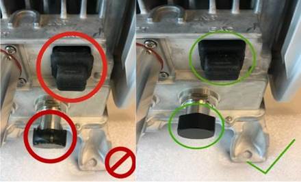
Figure 4 Caps and Seals Replacement in a Radio Unit
2.- In case RF ports are isolated by insulation tape, check the overall condition of the isolation in the antenna and the radio side, and determine if it is required to remove old rubber and apply new isolation to the ports, perform the same procedure to the Power port in the Radio Unit. Figure 5 shows the RF port isolations of a 4X4 MIMO configuration.
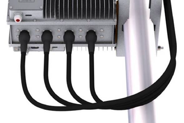
Figure 5 RF Ports seals in good conditions
3.-Check the Radio Unit mounting fixing screw tightness. Tight all the loose screws to the torque value specified in the respective product installation manual and replace any damaged screw. Figure 6 indicates the fixing screws of a radio unit mounting kit.
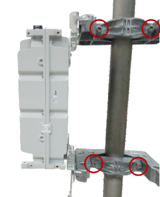
Figure 6 Radio Unit Mounting Fixing screws
4.-Check the fixing screws of the antenna mounting, the mechanical tilt and azimuth must be verified and compared with the site documentation, in case of mismatch readjust the Mechanical Tilt and Azimuth as indicated by the antenna installation procedures. Figure 7 shows the elements that should be verified during the antenna inspection.
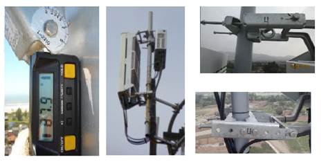
Figure 7 Antenna Mounting Verification
5.-If Microwave transmission is used, check the IF cable and/or Power Cable isolation in case of an All Outdoor Configuration. Figure 8 shows the isolation of the IF cable and the Power Cable.
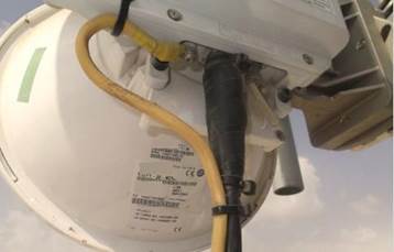
Figure 8 Seals on a Microwave connections
Baseband and Transmission System Preventive Maintenance Procedure:
1.-Ensure the fan units are clear of objects, in case of the presence of dust in the fan outlets it must be cleaned. The figure below shows the air outlet of an indoor Baseband in optimal conditions. Figure 9 shows the fan outlets of a radio baseband.
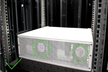
Figure 9 Baseband’s clean fan outlets
2.-Check the Isolation of the cabinet or shelter, especially in cable entrance, check the isolation of the cable entrance. There is no presence of water inside the cabinet or shelter, in case it is detected, proper corrective actions must be performed as soon as possible. Figure 10 shows the cable entrance of a cabinet properly isolated.
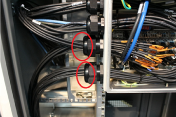
Figure 10 Cable entrance of an IP65 Cabinet
3.-Check the Overall Condition of the cabinet, look for dents, cracks, holes, or corrosion on the surface of the cabinet and whether the lock is normal, and the door can be opened and closed easily. Figure 11 shows an IP65 cabinet in good condition.
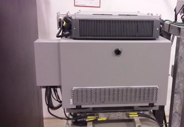
Figure 11 Baseband Cabinet in good conditions
4.- Perform an alarm validation of the site, all baseband and transmission equipment include LEDs that indicate abnormal status, validate with NOC and check locally the alarms and clear them if its possible. Figure 12 shows the alarm indicators of a baseband board.
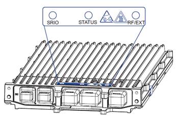
Figure 12 LED indicators of a baseband board
Power System: Electric Installation, Rectifiers and Batteries.
1.- Check the connections of power cables, the power cables are not aging, and there is no corrosion on the connection points. Figure 13 shows an Outdoor Power Distribution Unit Connection in good conditions:

Figure 13 Power connections properly isolated
2.- The rectifiers input voltage should not exceed their operative voltage, and their output must not exceed the operative voltage of the system, in case Field Technicians detect voltage variations corrective actions must be scheduled with the Dispatcher/ Field Management. Figure 14 shows the input power measurement using a multimeter.

Figure 14 Input power measurement
3.- Check the GND cable and grounding bar. Ensure that the connections of the GND cables are solid with no corrosion on them. Figure 15 shows the grounding connections of a cabinet.
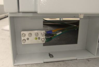
Figure 15 Grounding Connections in good conditions
4.-The batteries must be verified including the connections condition and the battery capacity, which measurements must be within the normal range. Figure 16 shows a battery array in good conditions.
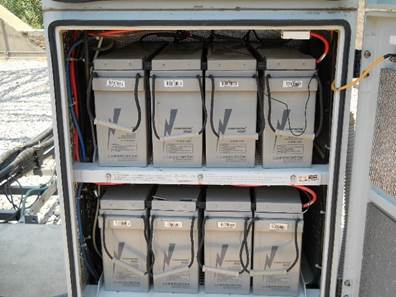
Figure 16 Battery connections in good conditions
5.-The overall condition of the facilities must be inspected by the Field supervisors ensuring that the fences, tower, ladders, shelters in case there is one in the site, remain clean without corrosion and is in good conditions, in case Field technicians note a degradation of the facilities, they may perform the actions that dont affect the service such as painting or sealing with non-invasive products like sealant paste. If field technicians note that it is required any corrective actions beyond what they might perform then the Dispatcher/ Field Management must be notified.
3.2.1.5 Corrective Maintenance Instructions
Due to the unexpected characteristics of a corrective intervention, the Corrective Maintenance Instructions must contain guidance to prevent more problems during any corrective intervention, including replacement instructions of the hardware elements of the cell sites such as antennas, radios, transmission equipment, baseband boards, power system and cables.
NaaS Operators may use the content of $$link$$Section 3.1.2 to elaborate their Corrective Maintenance instructions in the Maintenance Manual in addition to the replacement instructions provided by the vendors of each site element. Below an example of Corrective Maintenance Instructions for board replacement is presented.
Baseband Corrective Maintenance Instructions:
Pre-requisites
Electrostatic Discharge (ESD) can damage the baseband boards. Field Technicians must wear an ESD wrist strap or use a corresponding method when handling the baseband boards.
Field technicians must ensure that there is a backup configuration file of the baseband and transmission configuration, they must call the NOC to ensure such file is available and contain the last backup file.
Procedure:
1 Disconnect the DC mains power breaker.
2 Disconnect the cables keeping a connection map that shows the connections.
3 Unscrew the two baseband board screws as is indicated in Figure 17:
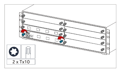
Figure 17 Unscrew baseband board
4.-Open the two baseband board extractors as is indicated in Figure 18.
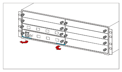
Figure 18 Opening the board extractors
5.- Pull out the baseband board from the chassis as is indicated in Figure 19.
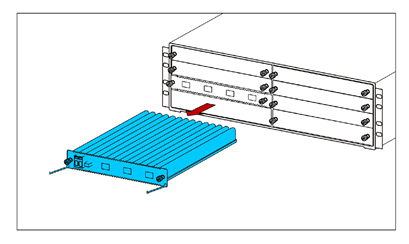
Figure 19 Pulling out a baseband board
6.-Open the extractors in the new baseband board.
7 Insert the new common baseband board carefully into the chassis and close the extractors as is indicated in Figure 20.
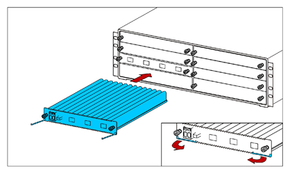
Figure 20 Inserting a baseband board
8.-Tighten the two screws by hand, and then tighten them to 1 Nm, using a TX10 screwdriver as is indicated in Figure 21.
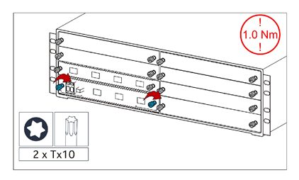
Figure 21 Tighting the screws of a baseband board
9.-Cable the baseband board as it was cabled before the replacement. The same cables must be connected to the same ports. Remember also about clamping the DC cables and the GND cables.
10.-Load a backup commissioning file to the Local Maintenance Console after plugging in the module.
Closing Activities
Field Technician must verify with the NOC if there are more alarms, clear all of them and create a final backup-commissioning file.
Please note that this module provides a Maintenance Manual Template to be adapted by NaaS Operators following the maintenance procedures required for each equipment that compose their cell sites.
3.2.2 Maintenance Intervention Report
A Maintenance Report will help NaaS Operators to create a Maintenance History which accurately leads to failure prevention and drives awareness about equipment maintenance.
The Intervention Report can be done through a Dispatch Tool, a Service Management Tool, or storing the reports that are generated manually. The analysis to properly select the Reporting method is deeply analyzed in the Module Field Force Management.
Regardless of the reporting method, a properly reported intervention should include enough elements that prove the intervention was performed correctly. Below the minimum requirements that NaaS operators should consider as part of the Maintenance interventions reports are listed:
This module includes a Maintenance Intervention Report Template to be adapted by NaaS Operators in case they decide to store their Maintenance Reports Manually.
1 Core Site Maintenance Introduction
Core Site Maintenance refers to all the actions performed to prevent a piece of equipment from failing, or to replace/repair a failed or damaged piece of any equipment that supports the Core site. Regular equipment maintenance ensures that each device runs efficiently during its intended life span. However, unplanned failures still may happen. To address these two issues, maintenance practices are categorized in Preventive and Corrective Maintenance.
The primary goal of Preventive Maintenance is to avoid the potential failure of the Core equipment. A Preventive Maintenance schedule is adopted to maintain all the elements that support the core sites in a satisfactory operating condition through systematic inspection, detection, and correction of the failures on the equipment. Preventive Maintenance increases the equipment life expectancy, minimizes malfunction risks, and reduces emergency repair. Preventive Maintenance is performed regularly on power supplies, grounding system, lightning protection, cooling, heating, and ventilation systems, supporting structure and ancillary equipment. However, even when the preventive maintenance will reduce the possibility of potential failures, they can still occur.
Corrective maintenance is the set of actions performed to rectify and repair faulty systems and equipment. The purpose of corrective maintenance is to restore broken down systems or equipment. Corrective maintenance is initiated when a problem is discovered on the Core System. For example, as part of a power outage, or in the process of conducting preventive maintenance, corrective maintenance is planned and scheduled as soon as possible. During the execution of corrective maintenance work, the asset is repaired, restored, or replaced.
The Core Site Maintenance Module provides the NaaS Operator with recommendations and best practices for preventive and corrective maintenance for their Core sites and guides NaaS Operators to prepare their reports that will evidence each maintenance intervention ensuring an overall good condition of their Core sites.
The main deliverables that the NaaS Operator will be able to generate through the use of this module are Preventive Maintenance Checklists and Reporting templates, which are basic documents that indicate the activities to be performed on the site and define standards to evidence their maintenance interventions.
1.1 Module Objectives
This module will introduce to the NaaS Operator the process and best practices to perform preventive and corrective maintenance of Core sites as required by the NOC and/or Field Force Management.
The specific objectives of this module are to:
1.2 Module Framework
NaaS Runbooks Framework shown in Figure 1 displays the Runbook modules and their relationship to the Core Site Maintenance Module.
After the Deployment Stream, the Operations & Maintenance module provides the necessary guidelines to establish the operational processes, which in turn, have a direct impact and influence on many aspects of the Field Maintenance Stream.
The Core Site Maintenance Module is included within the Field Maintenance stream. It takes inputs from the Field Force Management, and Network Operation Center on the Operation & Maintenance Stream.
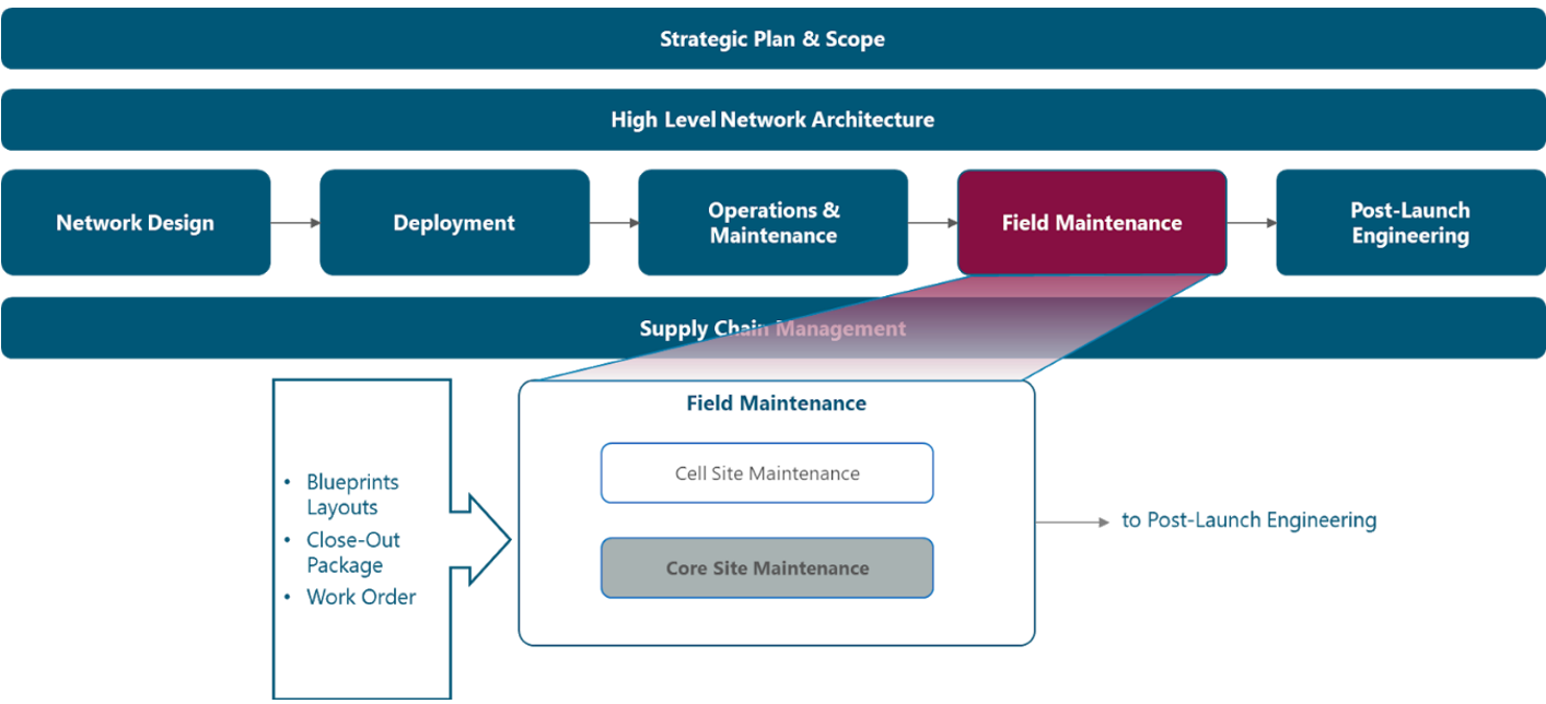
Figure 1 Network Design Framework.
Figure 2 presents the Core Site Maintenance functional view where the main functional content of the module is exhibited.
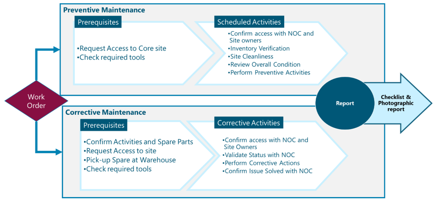
Figure 2 Core Site Maintenance
The rest of the module is divided into two sections. Section 2 contains a high-level view of the Core Site Maintenance Process, its prerequisites, and relations with the Field Force Management and NOC operations. Section 3 contains a high-level description of the key tasks to be performed as part of the Core sites preventive and corrective maintenance, including the implementation guidelines to create Maintenance programs through Training materials and Maintenance manuals. Additionally, Section 3 provides a detailed how-to instruction to report the maintenance interventions on the Core Sites.
2 Core Site Maintenance Process
Core Site Maintenance comprises a set of activities and best practices performed by Technicians, coordinated by the NOC and Dispatch & Coordination function, as indicated in the Field Force Management Module. The objective of this module is to perform the required tasks to prevent or correct malfunctions at the Core Sites. This section contains the procedures and best practices to be performed during Core Site Maintenance by the Core Site Staff.
2.1 Core Site Maintenance Process
Core Sites are constantly monitored by the NOC personnel, looking for any alarm or unwarranted condition that may have an impact on the network. In Case of a Critical Event is detected by the NOC, a Maintenance intervention is triggered by a work order provided by the Dispatch & Coordination Function within the Maintenance team. A work order is a document that provides all the information about a maintenance task and outlines a process for completing that task. Work orders can include details on who authorized the job, the scope, who its assigned to, and what is expected from it.
Due to the Criticality of Core the Equipment, it is common to have assigned staff in the Core Sites who perform routine Maintenance. However, Core Sites may not belong to Naas Operators and assign staff to the Core Site may not be possible. As an alternative, deeper inspections must be performed periodically to ensure the Service Continuity, this is called Preventive Maintenance (PM).
Corrective Tasks are triggered when the NOC detects a fault in a Core Site, or during Preventive Maintenance activities. In the latter case, Core Site Staff detects that Corrective actions are required, notifying Dispatcher/Field Management to schedule the required Corrective Intervention.
In both cases, a Maintenance report must be generated by the Core Site Staff after any Core Site Intervention and must be stored to keep a Maintenance record. This process is illustrated in Figure 3.
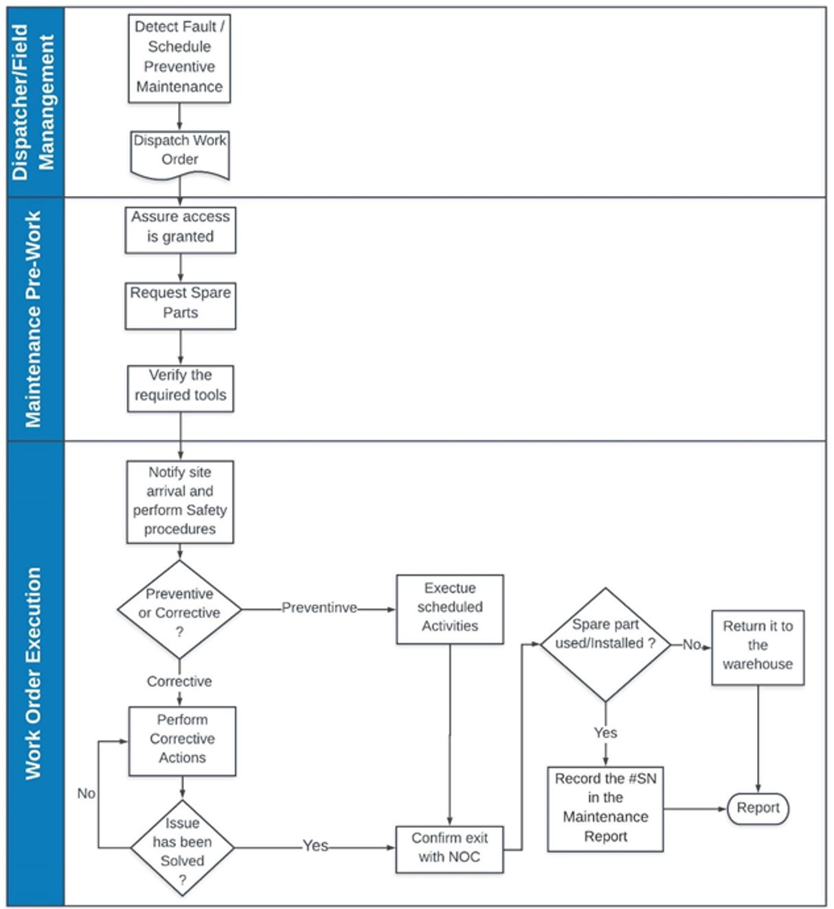
Figure 3. Core Maintenance Process
In order to guarantee a successful Maintenance Intervention, Core Site Staff must perform a set of tasks before each maintenance intervention, the following subsections contain the best practices to prepare the Maintenance Interventions.
2.2 Preparation for the Maintenance Intervention
Once the Work Order is dispatched, Core Site Staff must request the spare parts, ancillaries and other miscellaneous materials required for the Maintenance Intervention. This request is triggered directly by the Core Site Staff with support from the Network Operation Center. The Spare parts must include a list of the Ancillaries that will be required to perform the Maintenance Interventions (as indicated in vendor documentation). This will ensure that Core Site Staff have everything to perform their maintenance intervention.
The Preparation of the maintenance intervention is of paramount importance since will enable Core Site Staff to perform the maintenance interventions at the expected time, avoiding delays during reworks, below are listed some consideration to prepare the maintenance interventions:
2.3 Work Order Execution
Execution of the work order should follow a set of tasks to diminish the risks involved in performing a Maintenance intervention. A Work order execution procedure ensures that the maintenance is performed properly, protecting Technicians of possible injuries and prevents potential damage to the equipment. Below are listed the recommended tasks to execute a work order:
The following section details the Maintenance Guidelines, which instruct NaaS Operators to implement the Maintenance Process for their Core Sites.
3 Maintenance Guidelines
This section provides a descriptive overview of the Core Site Maintenance Procedures, including Preventive and Corrective interventions and recommended actions for each case. Additionally, this section includes implementation guidelines that NaaS Operators may consider elaborating their maintenance manuals to standardize their maintenance interventions.
3.1 Maintenance tasks description
In order to guarantee a successful maintenance operation, Technicians must perform a set of tasks before, during and after each maintenance intervention. This section describes the required tasks to be performed during the Preventive and Corrective Interventions.
3.1.1 Preventive Maintenance.
The Preventive Maintenance (PM) implies the condition assessment of certain items, considering a reference standard to diminish the probability of potential failures. The Preventive Maintenance Schedule is planned following different strategies, as is detailed in the module Field Work Management.
At the basic level, PM can be deployed as a strategy to improve the availability performance of a particular data center component. At a more advanced level, PM can be leveraged as the primary approach to ensuring the availability of the entire data center power system (generators, transfer switches, transformers, breakers and switches, PDUs, UPSs), cooling system (CRACs, CRAHs, humidifiers, condensers, chillers) and Core equipment (Servers, Storage, Switches and Routers).
One of three results can be expected during a PM visit:
The following subsections contain a General Description of the Preventive Maintenance tasks for each element on a Core Site, categorized in Power System, Air Conditioner System & Shelter Environment and Core Equipment.
3.1.1.1 Core Equipment Preventive Maintenance.
The Core Equipment include Servers, Networking equipment, Storage, and data cabling. Table 1 provides the maintenance items, condition assessment, reference standard, and service required of a Core Equipment for a Core Site. Please note that in most cases, the SW Maintenance is performed by NOC.
|
Recommended Schedule |
Condition Assessment |
Reference Standard |
Service Required |
|
Daily |
● Check for visual alarms with the LED indicators |
● There are no alarm indicators |
Contact NOC/Field Work Management |
|
Monthly |
● Verify the backups are working. ● Check disk usage. ● Update Control Panel firmware. ● Check application updates. ● Check remote management tools. ● Check server utilization. ● Review user accounts. ● Check system security.
|
● Create Backups Daily
● Delete logs and s/w versions that are not in use
● Change passwords
● Update the OS as is required.
● Update Management Tools |
Contact HW and SW provider in case of high server utilization or SW Malfunction.
|
|
Monthly |
Visual Inspection |
Fans and air outlets are clean |
Clean dust using an air blower, ensuring enough space to not damage circuits.
|
|
Quarterly |
Check that unused Ports and fibers have protective caps |
All Unused Ports and fibers are properly protected |
Install caps in unused ports and fibers |
Table 1 Core Equipment Preventive Maintenance
3.1.1.2 Power System Preventive Maintenance
The Power System consists of Uninterruptible Power Systems (UPS), Power Distribution Units (PDUs), Power Supply Units (PSUs), Grounding, and a Power Generator. In case NaaS Operators own one, it will also include the Automatic Transfer Switch. While some basic maintenance tasks such as visual inspections can be performed by NaaS Operators staff, the majority of services require a trained technician from the power system vendor organization, both for the expertise required and also to ensure personnel safety.
Table 2 shows a recommended UPS/PDU maintenance schedule. Please note that the Service is only executed if the item does not comply with the reference standard.
|
Recommended Schedule |
Condition Assessment |
Reference Standard |
Service Required |
|
Monthly |
● Visual Inspection ● If a battery monitoring system is in place, review the results ● Measure the battery float charging current |
● All system components are clean ● Input, Output and bypass voltage and current values are within designed specifications. |
● Clean boards using an air blower, ensuring enough space to not damage circuits. ● Contact UPS Provider if Voltage is not within designated specifications. |
|
Quarterly |
● Visually inspect equipment for loose connections, burned insulation or any other signs of wear. ● Measure the voltage of each cell or battery block. ● Visually check for liquid contamination from batteries and capacitors. |
● Power Ports are correctly connected and insulated ● Input, Output, and bypass voltage are within designed specifications. ● Batteries do not produce excessive heat |
● Tight loose connections following vendor procedure ● Clean Battery connections following vendor Specifications ● Contact UPS Provider Capacitors shows any leak. |
|
Twice a year |
● Check UPS Firmware |
● The Firmware is updated |
● Update Firmware as required. |
|
Yearly |
● Inspect UPS/ PDU components ● Conduct thermal scans on electrical connections using a diagnostic tool ● Measure and check the torque of all connections. ● Load-test the battery bank disconnecting the UPS from its power source. For flooded-cell batteries, the technician should: ● Inspect terminals for signs of corrosion and accumulation of dirt ● Measure and record the voltage and current of the entire bank ● Measure and record the voltage for each individual cell and test their electrolytes ● Record and log measurements to track battery performance |
● There are no signs of corrosion and heat damage ● There are no hot spots in the UPS System ● All Power connection are tight with the right torque ● Batteries Float current are within designed specifications. There are no signs of corrosion and heat damage |
● Re-torquing any power connections as needed ● Clean signs of corrosions ● Replace batteries if it is required |
Table 2 UPS/PDU Preventive Maintenance
Table 3 shows a recommended maintenance schedule for grounding and electrical distribution service- Please note that the Service is only executed if the item does not comply with the reference standard.
|
Recommended Schedule |
Item |
Condition Assessment |
Reference Standard |
Service Required |
|
Monthly |
Fuses, Breakers, Barriers and Shutters. |
Visual inspection |
● There are no signs of burn-in Fuse and breaker. ● Proper clearances are maintained. ● There are no signs of excessive deterioration or overheating. |
● Install / Replace Fuses, Breakers ● Rearrange cabling clearances where it applies. |
|
Yearly |
Grounding
|
● Visually verify that a proper grounding wire is present and connected to the installation site grounding bar and the device. ● Perform a connectivity test between the device and the installation site grounding bar using a multimeter.
|
● Grounding wire dont show signs of corrosion ● Grounding bars are not burned ● Resistance is between 1 and 5 Ohm. |
● If the grounding wire is not present, put it in place. ● Replace Grounding wires if its required |
|
Yearly |
Yearly (Automatic Transfer Switch) |
Verify tightness of accessible bolted electrical connections; inspect all mechanical indicating devices for proper operation |
Perform all mechanical operational tests on both the circuit breaker and its operating mechanism; confirm the proper operation of interlocks and mechanisms. |
Contact Vendor Provider if there is sign of malfunction in the ATS |
Table 3 Grounding & Electrical Distribution Preventive Maintenance
3.1.1.3 Air Conditioner & Facilities Preventive Maintenance
Air conditioners and their associated subsystems, such as chillers, cooling towers, condensers, ductwork, and pump packages, are used to maintain the temperature and humidity within the allowed range. These devices must be periodically checked to verify that they operate efficiently and in accordance with the requirements of the installation site. Additionally, Illumination and protective devices must be periodically checked.
Table 4 outlines the tasks to perform the Preventive Maintenance on the Air Conditioning and Facilities of the Core Sites.
|
Recommended Schedule |
Item |
Condition Assessment |
Reference Standard |
Service Required |
|
Daily |
Core Site Room Environmental check |
● Measure room temperature and humidity. ● Check the system for adequate cooling. ● Check the Capacity to support the load. |
Temperature within 18 C to 27 C Relative humidity less than 60% Dew point within the range of 5.5 C to 15 C
|
-Adjust and calibrate Air conditioner and climate controls |
|
Monthly |
Air Conditioner
|
.-Inspect unit for damage, missing or broken hardware, and abnormal noises.
.-Inspect Air Filters
.- Check external paint integrity.
.-Inspect for foreign debris and signs of corrosion within the unit.
.-Inspect heat exchangers, fan blades, and coil fins.
Inspect for water leaks on the piping system.
.-Visual inspection for refrigerant and or Chilled Water leaks. Visually inspect the Water/Glycol condenser loop for leaks if applicable.
.-Inspect condensate pan and verify proper condensate removal from unit.
.-Check fan speed regulation and controls. |
.-There are no loud sound and broken hardware
.-Filters are clean. .-Paint is in good condition .-There is no sign of corrosion
.-Coil Fins and blades have no damage
There are no water leaks
.-Refrigerant or water levels are within the operative levels.
.-There is no excessive amount of water and there is no presence of rust.
.-Fan operates normally |
–Replace drive belts, lubricate bearings
.-Clean or replace the factory-installed air filter and water filter media.
.-Clean or replace the humidifier cylinder. Inspect humidifier water valves.
.-Tight electrical connections within the unit.
.-Tighten pipe clamps, piping joints, and compressor mounting hardware within the unit.
.-Adjust fan speed regulation and controls.
.-Repair Leaks as provider maintenance recommendation. .-Fill water supply provider maintenance recommendation.
|
|
Twice a Year |
Illumination in the Core Site |
Check whether the routine and emergency illumination in the equipment room is normal. |
The illumination works properly |
Look if fuse or light breakers are switched on, notify Field Management for any malfunction. |
|
Yearly |
Protective devices |
Check whether anti-disaster devices, equipment protection devices, and fire protection devices are in good condition. |
-The foam extinguisher or dry powder fire extinguisher is installed in the equipment room. The pressure and validity period of the extinguisher meets the requirements -There is no danger of damage to the equipment by rats or insects. |
Replace or fill the extinguisher |
|
Monthly |
Core site Cleanliness. |
Check whether cabinets, equipment housing, equipment interior, tables, floor, doors, and windows are clean |
All the items to be checked are clean. |
Clean the Core site Interior, looking for possible leaks. |
Table 4 Air Conditioner and Core Site Preventive Maintenance
NaaS Operators may consider including as part of their operations procedures a Preventive Maintenance Checklist to help Technicians to perform Preventive Maintenance on their Core Sites.
3.1.2 Corrective Maintenance.
Corrective Maintenance can be triggered by the preventive inspections, which detect that corrective actions are required and will require service interruption such as cabling replacement. However, corrective actions are triggered as well in case of unexpected failures. In this case, the Dispatcher/ Field Manager releases a work order that Technicians must review and understand before departure to the site. The following subsections include a high-level overview of the key tasks that the field maintenance team may perform before, during and after corrective actions.
3.1.2.1 Corrective Maintenance on Core Equipment.
When corrective actions are triggered to maintain the Servers, Storage or Networking Equipment, it must be likely to check a Critical Event that NOC could not solve remotely. The core site may be out of service if there is no redundant configuration installed. Technicians must perform certain actions before considering hardware replacement. Below are some considerations for corrective maintenance on Baseband and Transmission Equipment.
Pre-requisites
Procedure
If Core Equipment seems not to be energized:
If core equipment is on, but there is no connectivity between Core equipment and NOC:
Closing Tasks
In case that it is required to replace fan modules, some vendors specify that the fans can be replaced without interrupting the service if the baseband/transmission equipment is located in controlled environments that do not exceed certain temperature and the replacement procedure dont exceed 20 minutes.
3.1.2.2 Corrective Maintenance on the Power System
Any corrective action within the power system will be required to disconnect the main power supply to protect the technicians and the Core Site equipment. Below are some recommendations that NaaS operators may consider including them in their operational procedures:
Prerequisites
Procedure
If there is a complete power outage in the Core site:
If there is no power in the Core equipment:
Closing Tasks
3.1.2.3 Corrective Maintenance on Air Conditioner
Air Conditioner Corrective Maintenance can follow the same actions as was detailed in Section 3.1.1.3. However, NaaS Operators may consider specialists in air conditioning maintenance if the required repairs cannot be made by Core Site Staff. The recommended strategy for Facilities Maintenance is to hire maintenance services from the construction companies or Contractors. Field Management must keep track of the companies that provide these services, oversee the process, and ensure that the required maintenance is performed.
3.2 Maintenance Implementation
This section outlines the best practices to implement a Maintenance program that will ensure the intended lifespan of the Core equipment and standardize the procedures during the maintenance intervention in the core site using a Maintenance Manual. Additionally, this section describes the requirements to keep a Maintenance Record of all Maintenance Interventions.
3.2.1 Core Site Maintenance Best Practices
The Core site must support the Core equipment with the ideal conditions to operate optimally. Using Air Conditioning Systems and Power Systems are used to create the right environment and provide high-quality energy to the Core equipment.
However, installing Air Conditioner and Power Systems is not enough to ensure the intended lifespan of the Core equipment. Maintenance guidelines must be followed to protect the Core equipment against the elements that cause more damage to the equipment such as Dust, Humidity and Electrical Damage. NaaS Operators must ensure to protect their equipment following the next Maintenance Implementation guidelines:
3.2.1.1 Measures against Dust and Particulates
The following guidelines are recommended to minimize damage caused by dust and particulates:
If the measures taken to prevent the entry of dust and particulates into the installation site are not effective, consider performing periodic cleaning of the inner part of the data networking equipment.
To get access to the inner part of the equipment, follow the instructions that are outlined in the installation guides for the specific Core equipment, paying particular attention to the safety requirements. Once getting access, clean the dusty equipment as follows:

Figure 4. Clean Circuits with Air blower
Additionally, NaaS Operators should consider the following best practices during their Maintenance Interventions:
3.2.1.2 Temperature and Humidity
The following guidelines are recommended to properly maintain the temperature and humidity in the Core site:
3.2.1.3 Maintenance on redundant systems
As discussed in other modules, the core site is a critical location which always incorporates redundancy at the hardware level, not only for the core equipment, but for power supply, cooling, and emergency systems. Further details on redundancy design can be found in the Civil & Power Design for Core Sites and Mobile Core LLD modules.
A fully redundant system creates the possibility to perform maintenance without interrupting core site operations but requires additional procedures to properly maintain and test the Core equipment and supporting infrastructure. Below, the recommended guidelines to properly maintain redundant systems are provided:
3.2.2 Core Site Maintenance Manual
The Core Maintenance Manual is a document that includes the process that Core Site Staff must follow in order to perform their Maintenance tasks. NaaS Operators may consider as a reference, the content of Sections 2, Sections 3.1, and Section 3.2.1 to elaborate them.
Please note that the actual maintenance and replacement procedures are detailed by the vendor of each equipment as well as the required tools.
The elaboration of the Maintenance manual Should include the Next Outline:
NaaS Operators may refer to the Cell Site Maintenance Module to standardize their Maintenance Manual. This module provides the Preventive and Corrective Maintenance Example Instructions to be performed in the Core site. It must be adapted by the NaaS Operators, depending on their needs.
3.2.2.1 Core Site Preventive Maintenance Instructions
The preventive maintenance instructions should be detailed step-by-step in the Maintenance Manual as clearly as possible. NaaS Operators may use the content of Section 3.1.1 as a guide to elaborate the Preventive Maintenance instructions. Below is an example of the Preventive Maintenance Instructions for Core Equipment.
Core Equipment Preventive Maintenance Procedure:
1.- Check for visual indicators on the Core equipment, in case any fault is detected, contact NOC to verify the procedure. Figure 5 shows the Core Equipment Server with a PSU fault.
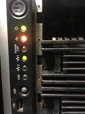
Figure 5 LED indicators in a Server
2.- Clean the inlet air grids in servers, storage, and network equipment, which usually do not have separate air filters. Figure 6 shows a Server with Dusty Inlets versus Dust-Free server inlets.

Figure 6. Server with Dusty Inlets versus Dust-Free
3.- Apply dust caps on all empty optical ports that are not in use. Cap the optical cable terminations as well. Noncompliance with this requirement can lead to adverse effects such as transmission errors. Figure 7 shows the unprotected optical ports of a router and unprotected unused Fiber connector.
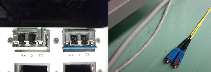
Figure 7. Unprotected Ports and Cables
3.2.2.2 Corrective Maintenance Instructions
Due to the unexpected characteristics of a corrective intervention, the Corrective Maintenance Instructions must contain guidance to prevent more problems during any corrective intervention, including replacement instructions of the hardware elements of the Core Sites such as UPS, PDUs cabling and Core equipment.
NaaS Operators may use the content of Section 3.1.2 to elaborate their Corrective Maintenance instructions in the Maintenance Manual in addition to the replacement instructions provided by the vendors of each site element. Below an example of Corrective Maintenance Instructions for board replacement is presented.
Core Equipment Corrective Maintenance Instructions:
Pre-requisites
Procedure:
To reduce the risk of electric shock or damage to the equipment:
To remove the component:
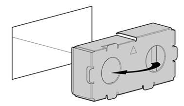
Figure 8. Removing a PSU from the Server
To replace the component, reverse the removal procedure.
Closing Activities
Technicians must verify with the NOC if there are more alarms, clear all of them and create a final backup-commissioning file.
3.2.3 Maintenance Intervention Report
A Maintenance Report will help NaaS Operators to create a Maintenance History which accurately leads to failure prevention and drives awareness about equipment maintenance.
The Intervention Report can be done through a Dispatch Tool, a Service Management Tool, or storing the reports that are generated manually. The analysis to properly select the Reporting method is deeply analyzed in the Module Field Force Management.
Regardless of the reporting method, a properly reported intervention should include enough elements that prove the intervention was performed correctly. Below the minimum requirements that NaaS operators should consider as part of the Maintenance interventions reports are listed:
1 Field Force Management Introduction
Field Maintenance refers to the teams that perform on-site interventions. Field Maintenance responsibilities include, amongst others:
While the Field Maintenance stream of the Playbook addresses the tactical and operational aspects of the tasks performed by the Field Maintenance Team, this module focuses on the corresponding management aspects.
This module presents an introduction to the functions, processes and systems that operate within the Field Maintenance team, and establishes guidelines for the NaaS Operator to define the structure of the Field Maintenance team, customize the processes that will be implemented, identify the tools that will support the operation, and select the implementation model to be followed along with the correct dimensioning of the Field Maintenance team.
1.1 Module Objectives
This module will immerse the NaaS Operator into the functions and processes of the Field Maintenance team and will provide the necessary directions to establish and manage the NaaS Operator Field Maintenance operations. The specific objectives of this module are to
1.2 Module Framework
The Playbook Framework in Figure 1 describes the structure, interactions and dependencies among different NaaS operator areas.
Operations & Maintenance stream comes after Network Deployment to oversee and support the on-going operation of the network, supported by Supply Chain Management.
The Field Maintenance team are the on-site hands that perform any field task as required by the Network or Service Operation Center.
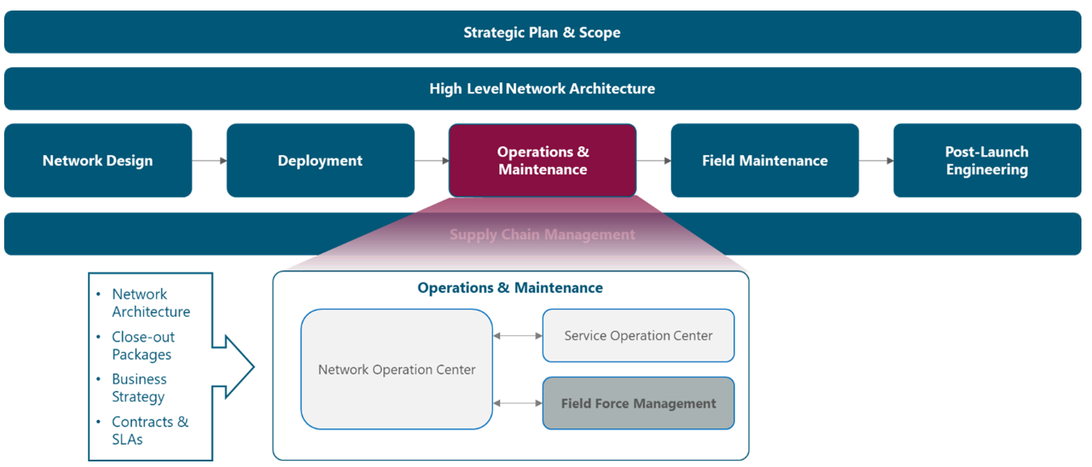
Figure 1. Module Framework
Figure 2 presents a functional view of the Field Force Management module where the main functional components are exhibited. Each function and its processes are discussed in sections 3 and 4 of the outline, while a high-level view on systems is provided in section 5.
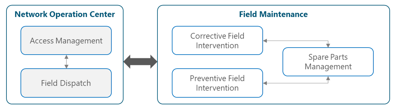
Figure 2. Field Force Management Functional View
2 Field Maintenance Fundamentals
This section provides a general overview of the Field Maintenance team, including the organization structure and the scope for each team highlighting the relevance and potential impact for NaaS Operators.
2.1 Field Maintenance Overview
Before diving into the overview of the Field Maintenance team, the term Maintenance will be reviewed. Maintenance is often referred to as the actions executed with the objective of retaining or restoring equipment to a state in which it can perform its required function. These activities ensure that production systems and equipment operate consistently in a steady state of defined functionality and performance.
The Field Force team, also known as Field Maintenance or First Line Maintenance, is the team responsible for all on-site activities on the network. Field Technicians are the eyes, ears, and hands of the Network Operation Center at any site, performing activities like:
The Field Force team is in charge of executing both corrective and preventive field interventions. Corrective interventions are the set of tasks performed to identify, isolate, and rectify faults on a failed equipment, which are commonly sent to Field Technicians via incident tickets created by the Network Operation Center organization. Preventive interventions are a set of tasks performed with a certain pre-defined periodicity (also referred to as scheduled or planned maintenance) to maintain equipment in satisfactory operating conditions, detecting and correcting incipient failures before they occur.
Field Maintenance is a crucial team on a network, as they serve as the vehicle to restore any on-site failure (corrective interventions) and to ensure optimum performance and prevent problems before they arise (preventive interventions). They are also in charge of spare parts handling and replacements performed at the site, when applicable. The NaaS operator must consider this team as a critical factor for their operation, since an efficient field workforce will enable increased business productivity and improved reputation by decreasing the turnaround time for repair services.
2.2 Field Maintenance Organization
From a functional view, the Field Maintenance team includes the following functions:
Both functions will be covered in depth in Section 3 of this module, where guidance will be provided for the NaaS Operator to define the structure that best matches the intended scope of the organization.
From a process view, the Field Maintenance team includes the following responsibilities:
These processes will be covered in depth in Section 4 of this module. The NaaS operator will be presented with alternatives to customize the processes according to its requirements and capabilities.
The teams working within the Field Maintenance organization coordinate their efforts with the Network Operation Center in order to prevent or minimize any unplanned interruption on the network or a reduction/degradation in the quality of the service delivered to the end-user. While the end-to-end flow will be presented in Section 4, a high-level overview of the interactions of the teams is presented below:
3 Field Maintenance Functions
This section presents the definition of each function executed by the Field Maintenance team, focusing on its vital aspects and the configuration possibilities for the NaaS Operator.
3.1 Field Maintenance Functions Overview
The subsections below provide a drill-down into the functions of the Field Maintenance team, analyzing the key success factors and relevance/need for each function:
3.1.1 Field Technician Activities
The Field Technician activities function is the most vital function that is supported by the Field Force organization. Field Techs take over site assistance on sites, commonly for 24 hours a day and 365 days a year (although other arrangements do exist, as 8×5, 16×5, etc.), performing tasks to resolve faults on-site or assist with on-hands support in troubleshooting efforts along with the Network Operation Center’s Tier 1 or Tier 2 engineers. The most common setup is to have a Field Technician crew consisting of at least two field techs working on a site at any given time; this is to facilitate work at height and for health & safety concerns in remote areas. However, the NaaS Operator may consider to have only one technician on site for simple preventive maintenance tasks that do not require work at height. From this point forward, every time a Field Technician is mentioned on this document it is translated to a Field Technician crew.
Field Technician function typically includes the following activities:
The most common metrics used to evaluate this function are:
3.1.2 Dispatch & Coordination Function
The Dispatch & Coordination function coordinates and dispatches work orders to Field Technicians, assuring that the Field Technician accepts the work order, is aware of the work order priority and begins to travel to the site. This function also handles site access authorization escalations to the Network Operation Center’s Access Management function to guarantee Field Technicians access to the site.
This function includes the following tasks:
The metrics that are generally used to evaluate this function are:
3.2 Field Maintenance Functions Selection & Customization.
The different options to customize the functions or teams that comprise the Field Force Management team will now be presented.
3.2.1 Field Coordinator/Dispatcher NOC Aggregation Setup
One of the most common aggregation of functions is performed by embedding the Field Coordinator/Dispatcher function into the Network Operation Center Tier 1 level functions. This translates into aggregating the Access Management and Field Dispatch functions into the NOC Tier 1 team.
This can prove effective when the NOC is monitoring a small network comprised of less than 250 sites (or if network monitoring is broken up into different regions, each one covered by a small team of engineers). In this scenario, the Tier 1 team will also be in charge of executing field dispatches (if necessary) and making the necessary adjustments to make sure that there will be access to the site for the Field Technicians.
As mentioned before, this option is best suited for region-based monitoring or for small networks, as the increase in functions makes them aware of all details for their respective sites, but in turn, the overhead associated with this setup may challenge the NOC Tier 1 team. The alternative configuration is to have a separate Field Manager or Field Dispatcher performing this function.
3.2.2 Field Force Leadership
Field Force Leadership duties include Field Force planning, controlling, steering, and reporting all aspects of Field Maintenance activities; management of Field Force organization and Field Force staffing; delegation and empowerment of Field Coordinators and team members. Within those duties, the following main activities are performed:
Figure 3 shows the most common structure for Field Force Leadership, which will be explained in detail in the following paragraphs:
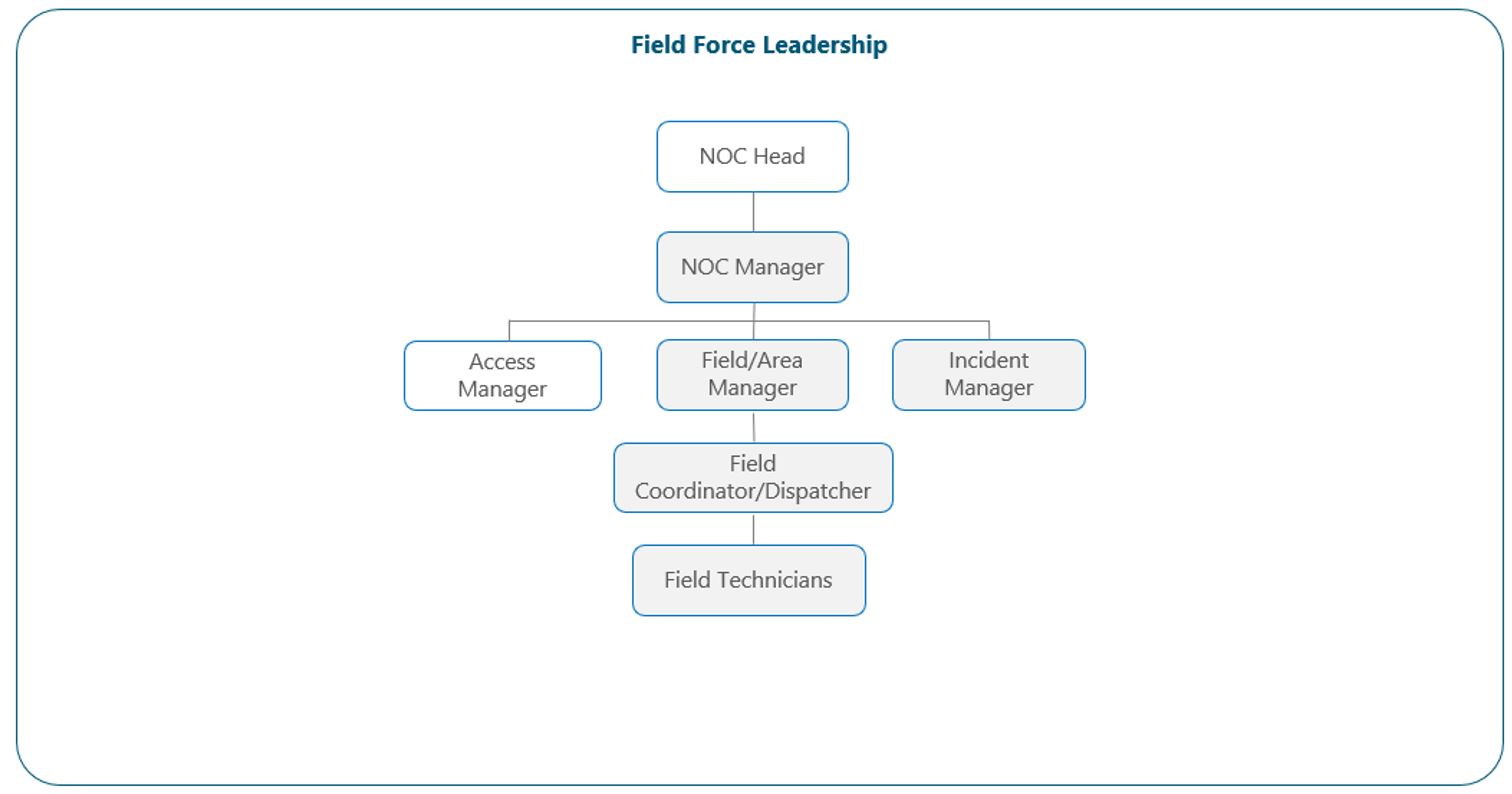
Figure 3. Field Force Leadership View.
As explained in Section 3.2.3 of the Network Operation Center module, each NOC group is usually supervised by a manager who delivers guidance to the entire team and serves as the Point of Contact (POC) for all those team’s requirements or escalations. The Field Force main POC is typically the Field or Area manager (or the Dispatch & Coordination team in absence of the former) who is usually in charge of all the Field Force structure, including the Dispatch & Coordination function and the Field Technician teams (who undertake the Field Technician activities function). The entire team is supervised by a NOC/SOC Head, who acts as the ultimate responsible for the NOC, SOC and Field Maintenance operations.
Field Coordinators are regularly set as part of the structure. These people’s expertise and process knowledge, supported by leadership empowerment, enables them to make controlled operative decisions during their shift in absence of the Field/Area manager. Field Coordinators usually respond to the acting Incident Manager on duty, who is the highest-ranking officer for any operative decision.
The NaaS operator may choose to leave out the Field/Area manager position in smaller networks, and thus the POC for field services would fall into the Field Coordinator’s team or to the NOC Manager in absence of Field Coordinators as discussed in section 3.2.1.
The Field Maintenance team configuration is further discussed in Section 6, in which the model to be implemented and the team design and dimensioning is presented.
4 Field Maintenance Processes
In this section, the core processes followed by the Field Maintenance team are reviewed, including end-to-end process flows, key elements, roles and responsibilities and the most common metrics used to measure each process success.
4.1 Field Maintenance Processes Analysis
The following subsections present an analysis of the processes executed by the Field Maintenance team, including rationale, common KPIs and roles associated with each process.
4.1.1 Field Intervention
As explained in section 3.1.1, the activities performed by the field force include:
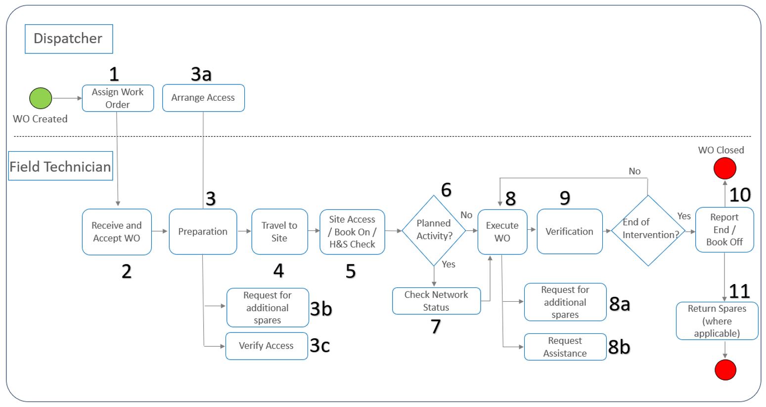
Figure 4 presents the High level, end to end process flow for the Field Intervention process
 ‘
‘
Figure 4. Field Intervention High-Level Flowchart.
The High-level flow is closely reviewed below:
The most common KPI’s utilized for Field Intervention are the following:
4.1.2 Spare Parts Management
Spare Parts Management is a particularly important process for the business, as the availability of a wide range of spare parts is a major factor for reduction in downtime when a hardware failure occurs. An efficient flow will guarantee that spare parts will be available for Field Technicians in the least amount of time to rectify a hardware failure occurring at the site at any given time.
This section focuses on the process performed by the Field Force organization, as other aspects regarding spare parts such as Stock Management are fully reviewed on the Logistics & Warehousing Module.
Figure 5 presents the High level, end to end process for the Spare Parts Management process
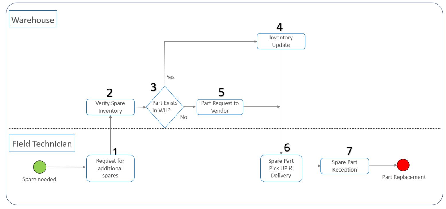
Figure 5. Spare Parts Management High-Level Flowchart.
The High-level flow is described as follows:
The most common KPI utilized for Spare Parts Management is the following:
4.1.3 Preventive Maintenance
Preventive Maintenance refers to scheduled, periodic maintenance of equipment to prevent unexpected breakdowns. This includes but is not restricted to tests, measurements and coordinated part replacements.
Preventive Maintenance is implemented through a schedule of planned maintenance with the aim of preventing breakdowns and failures. Preventive Maintenance can be a periodic activity, but it may also be a one-time activity. It can take the form of physical checks or logical activities like system backups. It ensures consumables such as equipment spares, are readily available should they be needed. Preventive Maintenance is not limited to physical checks, it should include regular system backups with offsite storage and checks for known errors as reported by the equipment vendors.
A Preventive Maintenance plan describes a list of activities to be performed on equipment according to a schedule – for example: daily, weekly, fortnightly, monthly, quarterly, and annually.
The primary goal of Preventive Maintenance is to avoid or mitigate equipment failures, and thereby reduce the cost that comes with corrective actions. This in turn will increase customer satisfaction. With Preventive Maintenance, it is ensured that all equipment is regularly checked and is ready for service when required.
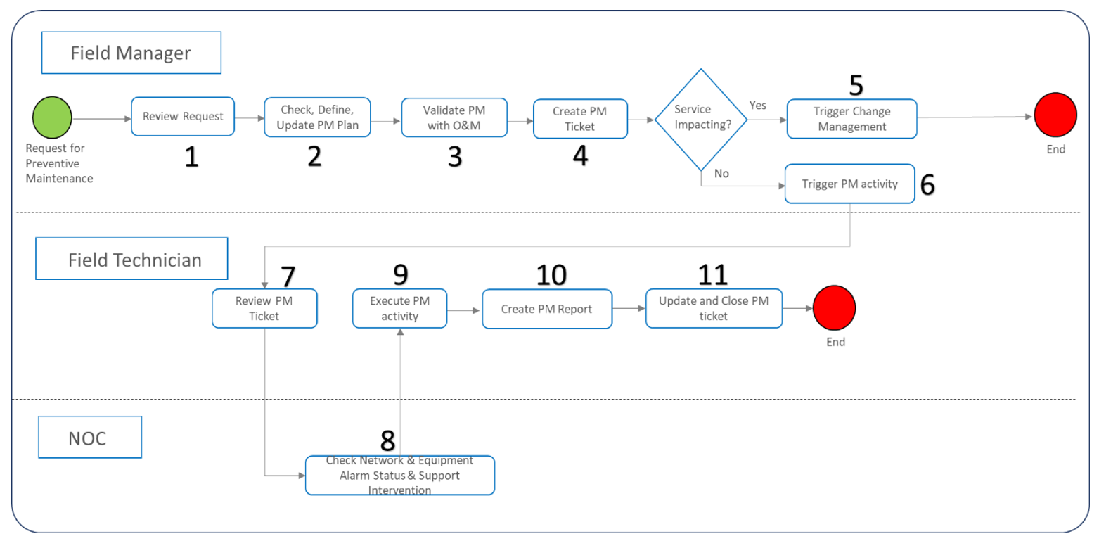
Figure 6. Preventive Maintenance High-Level Flowchart
The High-level flow for this process is detailed below:
The most common KPI’s utilized for Preventive Maintenance are the following: On-Time Preventive Maintenance and Preventive Maintenance Warranty.
4.2 Field Maintenance Process Selection & Configuration
Now that Field Maintenance processes have been analyzed, the NaaS Operator must select the processes to be implemented based on the Field Maintenance scope and the NaaS Organization capabilities and requirements.
Field Intervention is a mandatory process for the Field Force operation, as it is the main process followed by the Field Maintenance organization to troubleshoot and fix failures that are present on any site. Without such process in place, hardware failures would not be resolved, and service could be interrupted for the end-user, damaging the reputation of the NaaS operator.
There are two process adjustments that may be considered by the NaaS operator:
● Spare Parts Management
One option that may be considered by the NaaS operator is to remove the Warehouse from the Spare Parts process. Although feasible, this option is not recommended as this would translate into an absence of spare parts availability on a centralized, secure location. Alternatives are to have the Field Technicians stocking spare parts on their own which is not a secure option, or requesting parts directly with the vendor each time a spare part is needed, taking into consideration the time overhead this alternative implies.
● Preventive Maintenance
Another option that could be considered by the NaaS operator is eliminate the Preventive Maintenance process from the core processes executed by the field maintenance organization. This may become an alternative if the operator does not see fit to have a maintenance plan for the network, focusing on corrective interventions alone at least for the initial stages of the organization, or if the Field Technician team is comprised of a very few members and the operator does not want to have preventive maintenance activities occupying resources that could be focusing on corrective interventions.
5 Systems & Tools Overview
This section provides an examination of the systems and the most common tools used to support Field Maintenance, and aspects to consider for the NaaS operator evaluation and selection of tools to be incorporated into the field operations.
5.1 Tools High-Level View
There are three tools commonly used by a Field Maintenance organization to achieve its objectives. These are the Service Desk Management tool (which is also used by the Network Operation Center and the Service Operation Center organizations), a Dispatch Tool and a Network Inventory Management System (NIMS).
The Dispatch Tool can be regarded as the mandatory tool for the Field Maintenance team. While the SDM tool is a mandatory tool for the NOC and SOC, it can be viewed as an optional tool for the Field Maintenance team, as well as the NIMS tool. An overview of these tools is presented in the following sections.
5.1.1 Service Desk Management Tool
This tool is used for the documentation of all incidents, problems and changes that are being worked on the network at any given time. It can be considered one of the main tools used by the NOC and the SOC teams, as it enables the teams on both organizations to have a proper mechanism to document all activities surrounding each incident, problem or change ticket, including field interventions performed by the Field Maintenance Team.
A proper tool for documentation aids the team as they can know exactly what the status of any ticket is, what are the next items to be solved and what needs to be followed-up. It also enables reporting, which serves as the basis for Governance activities: revision of the Field Maintenance performance, KPIs, SLAs, etc.
A full Service Desk Management tool is a very powerful tool that incorporates modules for Incident Management (Incident tickets), Problem Management (Problem tickets) and Change Management (Change tickets). It also includes a Knowledge Base module (KB Articles) that serves as a repository for all the KB information used by all NOC, SOC and Field Maintenance teams, updated with key past experiences and lessons learned for future reference and improvements.
As discussed in section 5.1.1 of the Network Operation Center Module, another alternative to consider is to have a Ticketing tool instead of an SDM tool, if the focus will be set on fault restoral and less on Problem or Change Management. This option can be taken by the operator regardless of having a NOC/SOC/Field Maintenance structure in place as all three organizations could benefit from the SDM tool but other alternatives are available as well. This will be further discussed in section 5.2.
Examples of commercial tools are listed in Table 1.
|
Commercial Tools |
Free/Open Source Tools |
|
BMC Remedy ITSM |
OTRS Community ITSM |
|
ServiceNow ITSM |
CNTS C-Desk |
|
Cockpit ITSM |
Freshwork Freshservice |
Table 1. Commercial vs Free/Open Source Service Desk Management Tools
5.1.2 Dispatch Tool
This tool aids the Field Maintenance organization to manage the dispatch and life cycle of work orders generated to the Field Technicians, streamlining work requests management and reporting, which in turn, improves efficiency and productivity for the field maintenance team. This tool enables the dispatcher/coordinator function to ensure the right deployment for the right Field Technician is executed, and helps on planning, scheduling and tracking activities for the field force team.
The dispatch tool includes features such as job scheduling, route and location tracking, and usually includes dashboards showing work order status and SLA status for active and historical work requests handled by the field maintenance team. It also includes timestamps for the most common stages of a work order life cycle:
Commercial tools specifically tailored for telecommunications are Nokia myWFM, Ericsson WFM, Comarch FSM, Huawei WFM or Global Primex C2G tool. The NaaS Operator could also look for other available tools that are not fully telecom-oriented, but that could be adapted for their organization since they offer some of the features already covered. Finally, some free or open-source tools could work as alternatives for budget-constraint organizations.
Examples for all the categories above are listed in Table 2.
|
Commercial Tools |
Dispatch Software |
Free/Open Source Tools |
|
Nokia myWFM |
Synchroteam |
ServiceMax |
|
Ericsson WFM |
mHelpDesk |
ServiceTrade |
|
Comarch FSM |
RazorSync |
Tasker |
|
Huawei WFM |
eLogii |
|
|
Global Primex C2G |
AI Field Management |
|
|
WebFleet |
||
Table 2. Dispatch Tools
5.1.3 Network Inventory Management System
The Network Inventory Management System (usually known as NIMS) is a tool that aids the Field Maintenance organization to manage all the assets on the network. This enables the field area manager or the field coordinator/dispatcher to have records of all the equipment that is installed within the network, and have up-to-date the information accordingly with the changes or replacements that are executed by the Field Maintenance team.
The NIMS tool allows for a precise view of inventory status at any given time and ensures better control of the network assets. It is a useful tool that aids the field maintenance management team to know when to acquire new assets/spare parts or to decommission old ones, which can help with general network performance and uptime, along with capacity planning. This tool helps to keep track of equipment in a more efficient manner.
Examples of commercial tools are Ericsson Adaptive Inventory, Amdocs Cramer, Nokia Inventory Data Manager or Oracle Unified Inventory Management. Currently, there are no known open source or free tools that offer the same level of information and features as the commercially available NIMS tools, but the NaaS operator could explore available options such as Kuwaiba or Odoo Inventory to review if they can be adapted for their organization.
Commercial and open-source tools are listed in Table 3. It is important to note that open source or free tools may not have the same level of information and features of commercial tools, but maybe enough for the NaaS Organization needs.
|
Commercial Tools |
Free/Open Source Tools |
|
Ericsson Adaptive Inventory |
Kuwaiba |
|
Amdocs Cramer |
Odoo Inventory |
|
Nokia Inventory Data Manager |
|
|
Oracle Unified Inventory Management |
Table 3. Network Inventory Management Tools
5.2 Systems Selection
In the previous section tools that are part of the Field Maintenance solution were introduced. Now aspects to consider for tool evaluation and selection will be presented. First, the critical operational tools will be discussed, followed by optional support tools.
5.2.1 Critical Operational Tools
There is a tool that can be considered as critical and needs to be part of the Field Maintenance solution incorporated by the NaaS operator:
5.2.2 Support Tools
In the following paragraphs, the Service Desk Management and the Network Inventory Management System tools will be discussed, which are support tools that are optional depending on the needs of the NaaS operator.
● Service Desk Management Tool
A full Service Desk Management tool can be of great aid for the NOC and SOC teams (covered in both Network Operation Center module and Service Operation Center module), but the need for such a tool is very limited for the Field Maintenance team. If the Dispatch tool is in place in the organization, another benefit that usually spans from its use is that updates executed by the Field Technician are automatically synced in the ticket directly (whereas it’s an incident, change or problem ticket).
If such synchronization is not in place or if the dispatch tool is not acquired by the organization, the most common practice is to have the Network Operation Center team updating the ticket with relevant notes spanning from the interactions with the field maintenance team (usually via phone calls).
The NaaS operator can consider that there are free SDM tools available in the market, and some of them have open trials. By taking advantage of this, the Field Maintenance team could explore the tool to assess if its use is beneficial for their organization.
● Network Inventory Management System Tool
A Network Inventory Management System can bring value to an organization that handles a highly distributed spare part system or for an organization that handles several levels of warehouses (local, regional, centralized). It can also be beneficial for a NaaS operator that will keep in control not only the physical assets of the network, but also the software and configurations that are present for each element in the network.
If the NaaS operator considers that the cost associated is too high for the benefits it may bring, the operator could implement a much simpler network inventory system using available tools like Google Docs, Office 365 or Dropbox, keeping records and control of all spare parts using their associated spreadsheet tools This will make reporting for management more difficult, but is one of the most practical alternatives to keep control of the equipment that is physically present on a warehouse, and can also be used to keep control of the parts that are installed on the sites.
6 Field Maintenance Implementation
This section presents a discussion of the available implementation options and directives for NaaS Operators to define their own staffing model, service levels and dimensioning of the Field Maintenance staff.
6.1 Staffing Model Assessment
There are two main models available for Field Maintenance staffing (which apply to NOC and SOC staffing as well) that can be considered by the NaaS operator: In-sourcing (building Field Maintenance team with internal resources as part of the NaaS Organization) and Out-sourcing (reaching out to a third party to take control of field operations). An optional third alternative is also available, in which the NaaS operator may choose to outsource some tasks (such as the Field Intervention function) while retaining the other part of the operation (such as the leadership function, referred to as the Dispatcher & Coordination function).
Please refer to section 6.1 of the Network Operation Center module for a complete discussion on the Staffing Model Assessment, as the three models discussed there (Insourced, Outsourced and Mixed Schema) apply as well for a Field Maintenance staffing strategy.
6.2 Service levels Definition
Service levels are determined by the severity of the incident that has been created, which are assigned by the Network Operation Center organization. As such, the first thing that needs to be defined by the NaaS operator is the criticality matrix. Please refer to the Network Operation Center module for a complete discussion on the NOC’s service level settings.
After the criticality matrix is set, the NaaS Operator must set two variables for each category:
The first variable is strictly Field Maintenance dependent and is usually expressed in minutes (X minutes from dispatch creation to dispatch acknowledge and field tech assignment).
The second variable needs consideration of several factors, including average travel time, spare part pick-up, and the agreed contractual SLAs for new parts that may be required and that are not existent in the warehouse.
It is important to note that the SLA for the Field Maintenance Team will be closely related to the NOC SLA and NOC Response + Analysis time. For example, if the NOC SLA is 8 hours, the NOC response time is 15 minutes, and the NOC analysis time is 30 minutes, then the Field Maintenance SLA will be 7 hours 45 minutes.
Table 4 shows a generic example for Field Maintenance Service Levels.
|
Severity |
SLA |
Response Time |
Field Restoration Time |
|
Critical |
7 hours 15 minutes |
15 minutes |
7 hours |
|
Major |
11 hours |
30 minutes |
10 hours 30 minutes |
|
Medium |
22 hours |
60 minutes |
21 hours |
|
Minor |
44 hours |
2 hours |
42 hours |
Table 4. Field Maintenance Service Level Setting Example
In the case of the Field Maintenance organization, Service Levels for Spare Parts Management must also be considered. In this scenario, there are two categories that can be implemented: Critical Spare Parts, which are the parts that are identified as those required to resolve a site loss of service or the loss of a single equipment at the core/aggregation level, and Non-critical Spare Parts. An example of typical service levels for spare parts is shown in Table 5.
|
Criticality |
Part Availability |
SLA |
|
Critical Spare Parts |
24x 7 |
98% |
|
Non-Critical Spare |
8 x 5 |
90% |
Table 5. Spare Parts Service Level Setting Example
6.3 Team Design & Dimensioning
There are three common configurations to establish the Field Maintenance Organization:
● CONFIG 1
✔ Field Technician Activities are executed by Field Technician crews (each crew is comprised of two Field Technicians)
✔ The Dispatcher/Coordinator position exists
✔ On the Management side, there is one leadership position for Field Manager
● CONFIG 2
✔ Field Technician Activities are executed by Field Technician crews (each crew is comprised of two Field Technicians)
✔ The Dispatcher/Coordinator position does not exist
✔ On the Management side, there is one leadership position for Field Manager
● CONFIG 3
✔ Field Technician Activities are executed by Field Technician crews (each crew is comprised of two Field Technicians)
✔ The Dispatcher/Coordinator position exists
✔ On the Management side, there is no leadership position for Field Manager
The operator should choose the configuration that best fits the organization’s scope and purpose. After that, in order to establish an organizational structure, several factors need to be taken into consideration:
This information will aid the operator to estimate the dimensioning of the Field Maintenance team.
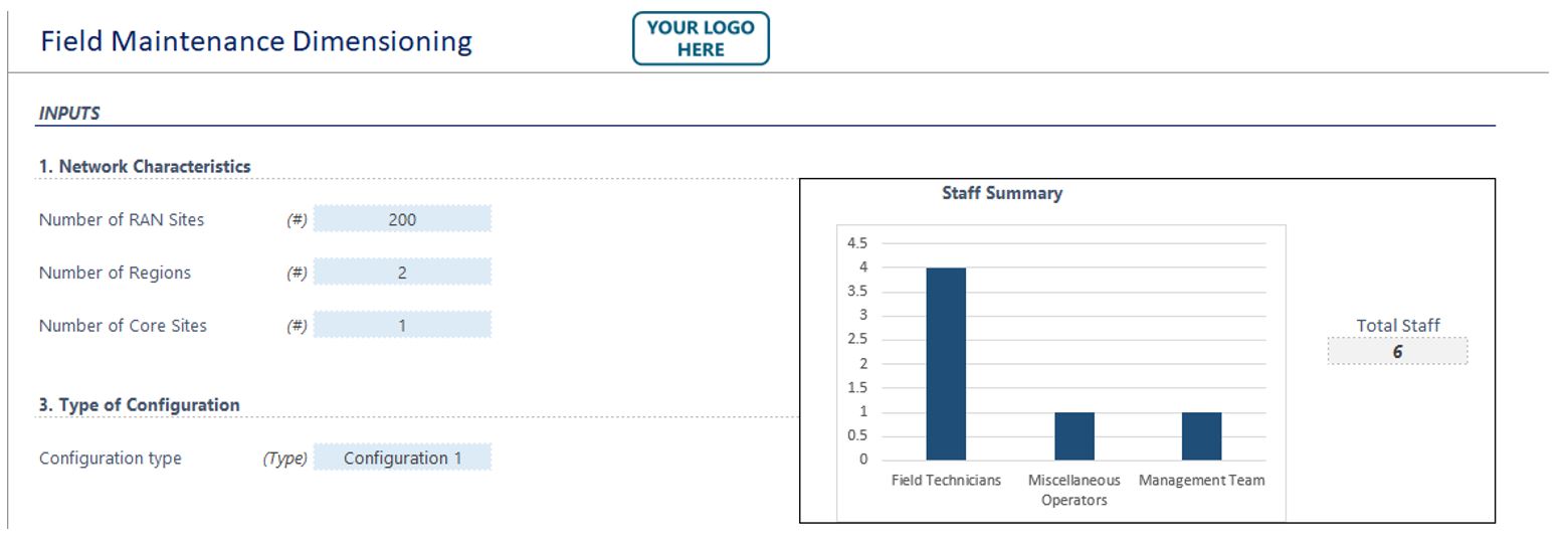
Figure 7. Field Maintenance Dimensioning Tool
Each of the inputs needs to be placed on the corresponding field. The first 3 fields (RAN sites, regions and core sites) are open, as shown in Figure 8:
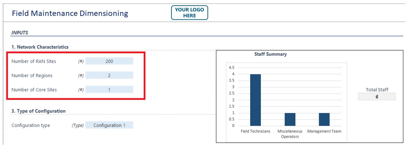
Figure 8. Open fields in the Playbook Field Maintenance Dimensioning Tool
While the remaining option which is configuration type has a combo box enabled to choose from the available options, or to define a custom configuration, as shown in Figure 9.
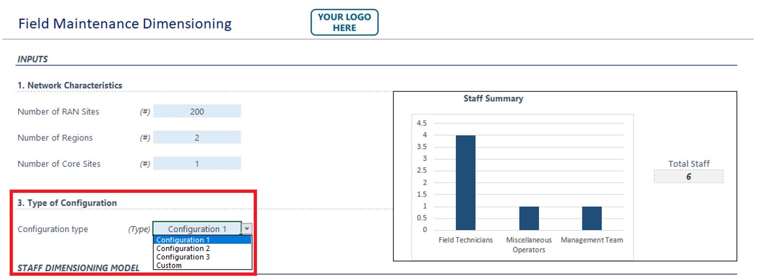
Figure 9. Combo box in the Playbook Field Maintenance Dimensioning Tool
Once all the fields have been completed, the tool will show a brief summary at the top showing the general number of Field Maintenance staff to be considered, as shown in Figure 10:
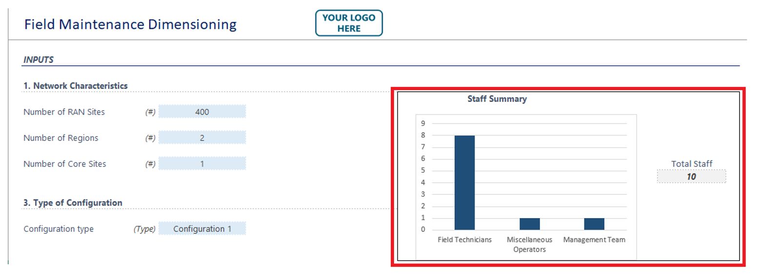
Figure 10. Staff Summary
Then a complete list of all the resources will be presented, including the Field Technicians, the Dispatch/Coordinator position and the Field Manager position as shown in Figure 11:
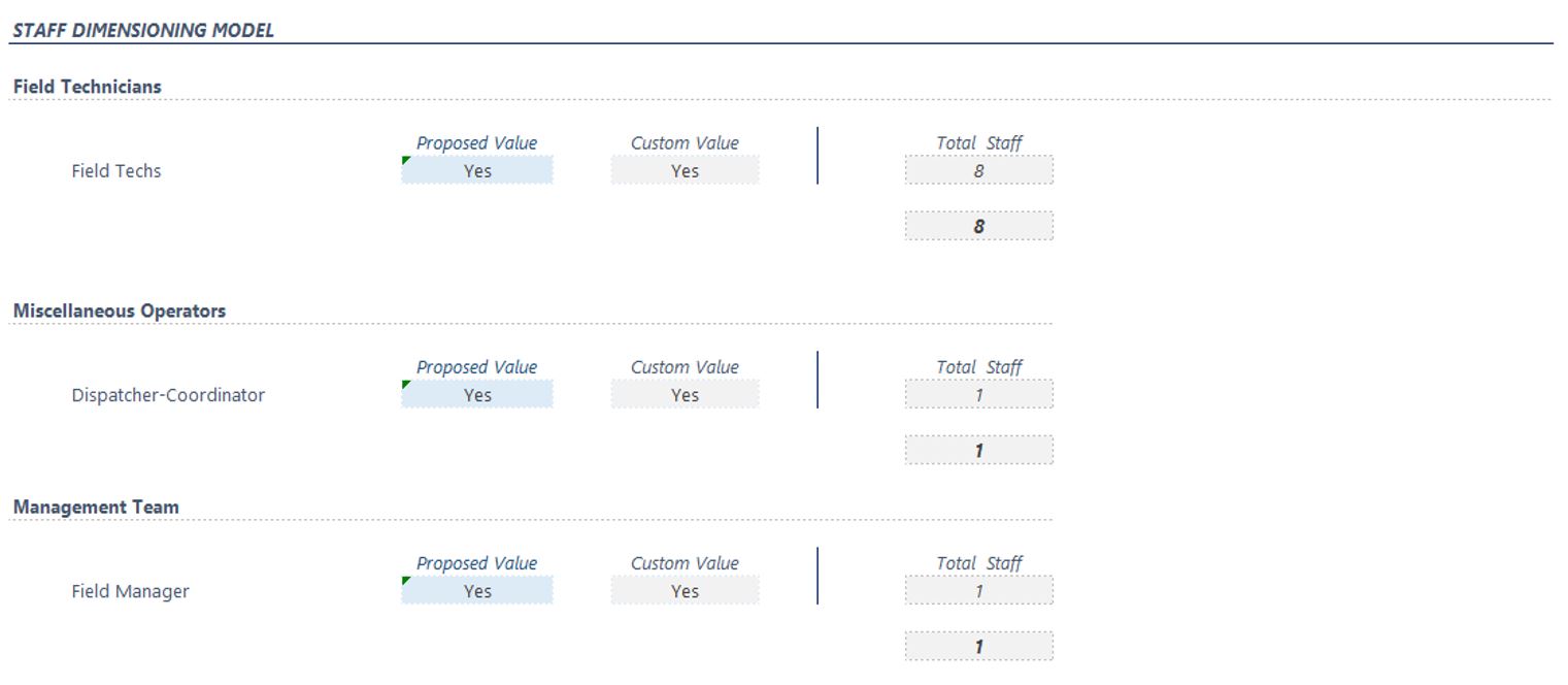
Figure 11. Field Maintenance resources
As seen in Figure 11, there are two columns named Proposed Value and Custom Value. Proposed Value is a flag set to indicate that the specific role is going to be considered as part of the team configuration. It is automatically populated based on the selected configuration.
In a similar vein, the Custom Value flag should be edited by the user when selecting the option for custom configuration (See Figure 10). Rows with value ‘Yes’ will be populated with the total number of staff resources, rows with value ‘No’ will be left empty.
Finally, it is worth mentioning that the tool is provided in Excel format which enables the NaaS Operator to change the underlying dimensioning assumptions based on their own experience or estimates.
6.4 Facility Design & Sizing
For the facilities, the operator needs to consider the peak number of resources that could be working on the Field Maintenance premises, according to the dimensioning performed on the previous section. The most common environment is to have Field Technicians working and reporting from their own houses, while the Field Manager or the Dispatcher are working on a centralized area or in the Network Operation Center facility.
In case the operator sees the need to have a centralized location for their field force, the operator needs to consider the office space that will be occupied. The office equipment needs to be considered as well (laptops, screens, desks, chairs), and also routing and switching equipment/ports need to be calculated.
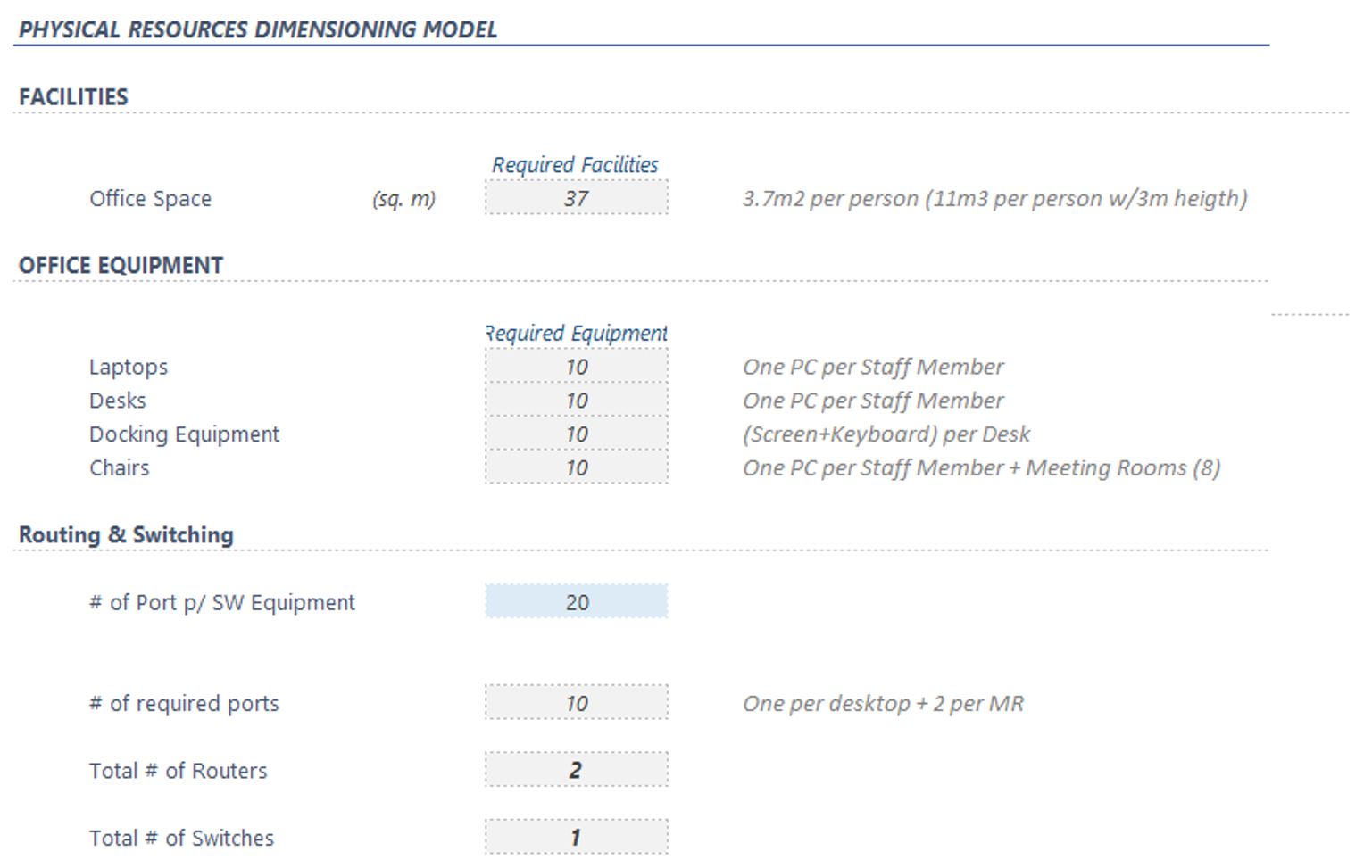
Figure 12. Playbook Field Maintenance Dimensioning Tool Facility Sizing
If the NaaS Operator does not consider that the Field Force team need a facility of their own, then adjustments for the Field Manager or the Dispatcher/Coordinator team should be included in the Network Operation Center facility design and sizing.
In any case, the NaaS Operator should keep in mind that the Field Technicians will have to be equipped with several tools needed for their day-to-day work, such as Screwdrivers, Hammers, Cutters, Crimping Tools, Knife, Drilling Machine, Punching Tools, RF Cable Cutter, Multimeter, Digital Power Meter, Ethernet Tester or a VSWR Meter. They will also need a Health and Safety package, including a Helmet, Safety Belts, Gloves, Boots, and a First Aid Box.