
Network as a Service (NaaS) PlayBook
1. Deployment Management Introduction
The Deployment Management module provides NaaS operator background information and methodologies to Plan, Control & Monitor a telecom deployment including: dimensioning guidelines that will help forecast a realistic Schedule, calculate the required resources and costs, analyze the project performance, forecast possible issues to propose possible solutions and communication methodologies to ensure engagement between all stakeholders within Deployment phase.
Deployment Management Module consists of three sections
- Deployment Process Overview
- Deployment Planning
- Deployment Control & Monitoring
Deployment Process Overview shows a high-level description of the deployment process from Network Design to site and network integration, acceptance and finally hand-over to operations.
Deployment Planning provides instructions, guidelines and best practices to ensure interworking of all stakeholders, coordination of different deployment phases and consolidation in a well-designed Deployment Plan.
Deployment Control & Monitoring will guide NaaS operator to manage all project phases, track all tasks and milestones, monitor all planned risks, mitigate possible issues and manage changes throughout the process.
This module makes reference to a Deployment Manager role. The Deployment Manager has the overall responsibility for the successful initiation, planning, design, execution, monitoring, controlling and closure of the NaaS Deployment. Each organization is different and Deployment management dedicated resources may not be within the organizational structure, if this is the case the role must be taken by someone else such as a Program or Project Manager.
1.1 Module Objectives
This module will enable a NaaS Operator to plan, orchestrate and manage the deployment of the network. The specific objectives of this module are:
- Provide an overview of the overall network deployment process, creating awareness of the tasks, stakeholders, timelines and dependencies that are part of this process.
- Provide instruction to perform a comprehensive and efficient deployment plan that ultimately contributes to speed up the time to rollout a NaaS Network under specific budget and resources.
- Guide the Naas Operator to monitor & control the deployment process, from acquiring the site up to delivery to operations.
Each of these objectives is tailored to meet the needs of NaaS operators managers during different phases of the project lifecycle.
1.2 Module Framework
The Module Framework in Figure 1 describes the structure, interactions and dependencies among different NaaS operator areas.
Strategic Plan & Scope and High-Level Network Architecture drive the strategic decisions to forthcoming phases. Deployment is the second step in the implementation strategy, and the same as other modules, it is supported by Supply Chain Management.
The Deployment Management module is included within the Deployment stream and its target is to coordinate and provide organization for the tasks in the rest of modules that impact network deployment.
Figure 1 Module Framework
Figure 2 represents the functional view of the module, where the main functional components to be orchestrated are exhibited. All these tasks will be planned, managed and controlled by the Deployment Manager throughout the deployment process.
Figure 2 Deployment Management Functional View.
2 Deployment Process Overview
This section presents a high-level overview of the main tasks, inputs, pre-requisites and requirements for the whole Deployment Process. From design, construction and network equipment installation; up to turn-up, testing and handover to Operations.
The Deployment Manager must ensure the availability of the inputs and resources to the various stakeholders in each stage. Tracking and storing all the inputs is part of the best practices of the deployment manager.
2.1 Network Design
Network design is the planning phase that comes before telecom infrastructure is implemented. It involves evaluating and understanding how all the elements of the network link together (from Radio Access Network, Transport Network, Mobile Core and Power Systems) and specifying their configuration so they can run as efficiently as possible. A well-designed network can bring increased operational efficiency.
Network Design refers to the definitions, classifications, objectives, constraints, network topology decision variables, and solution methods to create a Telecom Network. The different elements that compose the Network can be divided by RAN (Radio Access Network), Core and the Transport network.
Network design requires a set of inputs that should contain enough information & data needed to develop an accurate solution for each segment of the end to end network (For more information please see the specific design module).
Network Design inputs come from various sources such as outcomes from High Level Network Architecture Modules, Network Data, Site Survey Reports and commercial criteria.
Network Design process is split into two phases: High-Level Design (HLD) and Low-Level Design (LLD). The Split ensures efficient coordination with other tasks before starting the LLD.
2.1.1 Network High Level Design
HLD defines high-level characteristics of the network configuration, such as target geolocation, hardware type, transport solution and candidate sites. This function is carried out during the initial phase of the project, and its deliverables are used for budget estimation, contract negotiation and deployment planning.
2.1.2 Network Low Level Design
Once a site has been confirmed for deployment, Low Level Design (LLD) integrates deliverables including all the configuration parameters regarding RAN, TX, Power and Civil for each site. The Design team may release LLDs in batches for review, approval and transfer to deployment.
2.2 Site Acquisition
The scope of Site Acquisition phase is to obtain, within the shortest time possible, a cost-efficient permitted site ready for construction. The scope of site acquisition is divided into three major parts, namely Site Survey, Site Selection & Acquisition, and Site Permitting.
2.2.1 Site Survey
Is the activity to perform a study of the site facilities to ensure availability of space, backhaul and energy capabilities in existing sites, and site feasibility for greenfield installations. Site Survey reports will ensure site solutions are optimally designed and sufficiently documented, to be deployed on time and meeting the quality, health and safety requirements.
For new sites, the scope includes coordination with the network design team to discuss detailed site search criteria and any other special network planning or transmission planning issues. GIS-based pre-survey is conducted together with network planning, to identify a suitable search ring which is an area defined by a centroid and a radius (a fraction of the cell radius, usually less than 1 km). This area will be surveyed to find a suitable location for the sites to be deployed. Difficult search ring areas in terms of lease contract negotiations, road access and permitting should be avoided.
The site survey is arranged, to evaluate if the selected site candidates are suitable for construction and fit the search criteria and budget for lease negotiation. The resulting site survey report (SSR) specifies implementation requirements as well as transmission requirements including the line of sight survey (LOS), the site location details and coordinates, site owner details, ownership documentation, site type, access description, rental fee, sketch drawings, photos, building drawings, permit requirements and type.
For existing sites, evaluation activity includes the NaaS operator personnel to physically visit the site and contact the site owner or representative to ascertain necessary information or arrange specific existing site documentation from the operator.
2.2.2 Site Selection & Acquisition
After the site search, the two or three candidate sites are pre-validated and ranked based on network design, site acquisition and construction criteria, and the best candidate is preliminarily selected for lease negotiations and permit applications.
Based on the standard lease or frame agreement, the rental range for the specific area and the requirements for network planning, permits and construction works, the Site Acquisition negotiates the lease contract with the site owner.
The aim is to negotiate the standard lease contract without clause changes and at the lowest rental fee possible for this search area, as well as to select friendly sites in terms of owners who are open and willing to sign a contract. This will improve the process of permitting, construction works and implementation.
Site Acquisition Personnel which may be the Construction Service Provider or NaaS Personnel, should arrange and facilitate lease contract signature together with required legal entities (as per country law requirements). Once the lease contract is signed by the site owner/representative, the legal responsible will manage the process for signature by the NaaS Operator for completion of the lease. Lease contracts will meet local legal requirements.
Before signing the contracts, the legal responsible checks that all titles are legally confirmed, such as property title, land title and others, to assure that the owner of the site location is the legally relevant person to negotiate with. All necessary title verification documents will be collected and verified.
2.2.3 Site Permitting
Site permitting is a crucial point in the site acquisition process, as it aims to obtain all the necessary permits and sub-permits to build a site considering general permit requirements of the country and specific local requirements. The procedure can be contracted out to an external company such as a Construction Service Provider.
In any case, the NaaS operator must be aware of the required permits and oversee the procedure, since permits can run into issues, such as bureaucracy inefficiencies, social resistance or environmental issues, delaying deployment or requiring another nearby site to be found.
Final permit evaluation and arrangement for each site depends on each country and local laws. The NaaS Operator should have knowledge on local laws and practice to determine the documents that must be provided to the relevant authorities to obtain permission to build. The Deployment Manager and the legal team/responsible must evaluate the permit requirements and application process for each site separately.
After acquiring all necessary information and documents, site acquisition personnel submit the permit application to the responsible authorities. The result of the complete permit procedure is that the relevant local authorities grant, in a foreseeable timeframe, all permits necessary for site construction to start.
2.3 Procurement & Logistics
To optimize deployment, the NaaS operator shall leverage the complete ecosystem of infrastructure and services providers. The NaaS Operator shall define which providers are needed, and establish the selection criteria and engagement start dates, which in turn will be managed by the Supply Chain Management stream to reach deployment objectives. The Vendor Ecosystem for a NaaS deployment may include:
After Vendor Selection, each vendor is onboarded to the Deployment Project. Procurement orders and logistics are arranged based on processes defined in the Supply Chain Management modules of the PlayBook. The Deployment Manager should open a communication channel with Supply Chain and Vendors Management in order to track Purchase Orders, be aware of kitting procedures, International transportation up to last mile delivery process in order to forecast a proper schedule of the activities. The outcomes should include Agreements with a matrix of responsibilities.
2.3.1 Vendor Selection
Vendor Selection starts with a Request for Information (RFI) and/or Request for Proposal (RFP) for all the required vendors. This process is managed by the Procurement/Commercial Team as indicated in the RFx Process module of the PlayBook; however, close tracking by the Deployment Manager is necessary to give visibility to the progress or potential trouble for Procurement activities that could impact the start of Deployment Execution.
After Vendors submit their proposals, the corresponding department evaluates the proposals and submit the results. Deployment manager coordinate efforts with the Procurement Team to manage relationships, contracts and general communication with vendors.
2.3.2 Vendor Onboarding
After vendor Selection, vendor onboarding takes place to establish communication and coordination with the Vendors project managers, to establish reporting mechanisms, refine the schedule, and acceptance criteria. Other functions related to invoicing, contract management and payments are to be managed by the Procurement Team as detailed in the Supply Chain Management Stream of the PlayBook.
2.3.3 International Transportation
Vendors can export the equipment from several Countries to the Deployment Country by several methods including Sea, Rail or Air. Supply Chain management provides the design and orchestration of the supply network, integrating the forecast and anticipating the deployment needs and resources.
It also includes collaborative demand planning, order management for products and services, transportation and tracking for international and local operations, customs clearance, inventory management and integration of multiple supply chains if required.
Deployment Management should ensure a synchronized communication with the selected logistic service provider or equipment vendor for international transportation services optimization. And consider the arrival date of the Network equipment to the region (can be a local warehouse) in order to adjust the Schedules and forecast a realistic schedule for the upcoming deployment phases
2.3.4 Logistics & Warehousing
The Logistic & Warehousing is the method in which all the network equipment and ancillaries will be stored and distributed, NaaS operator must plan and manage the process and choose the strategy to implement it, between hire a 3rd party Logistic and Warehousing company or perform the process within the organization .
Whatever the strategy that the NaaS operator selects, Deployment Manager must ensure efficient equipment warehousing and inventory administration communication. It helps activities like demand forecasting, order placement, stockout alerts, goods tracking and replenishment.
2.3.5 Last Mile Transportation
Last Mile transportation is the process of shipping network equipment from the warehouse to the site location choosing the most efficient method to ensure a safe and delay-free delivery. The process goes hand to hand with logistics and warehousing and NaaS operator can choose between performing the process within the organization or hire a 3rd party Logistic and Warehousing company.
Deployment Manager should track the transportation of equipment, tools or any other project materials from Customer Warehouse/Drop off Point to site. If the arrival is correctly forecasted by the Deployment Manager, the schedule of the upcoming phases will be more accurate.
2.4 Construction
Construction shall be in accordance with NaaS operator requirements and standards following the site engineering design. The following high-level description of the potential site activities is provided for the purpose of managing and scheduling all other activities that depend on site construction.
Construction refers to the activities to construct a Telecom site and the Fiber infrastructure needed for transport transmission. In most cases, construction tasks are performed by a 3rd Party Construction Company, at least one construction company for sites and a different fiber construction company.
Construction is analyzed in 3 stages: Design, Preparation and Construction.
2.4.1 Site Design
Site Design activities provide site designs including ancillary materials. This includes guidelines on construction works for modernization of existing sites or new sites to be implemented to match the project-specific requirements.
Site Design is usually done by the selected construction company; however, the process should be overseen by the Deployment Manager. The process starts once the site survey report, and permits are complete, this will ensure that the final design of site facilities, fiber and power infrastructure fit the specified requirements. The outcome must result in a cost-effective site design, specification requirements and implementation guidelines compliant with legal and power company requirements avoiding a design rework.
2.4.2 Fiber Infrastructure Design & Construction
Transport connectivity from the RAN sites to the transport nodes can be done through microwave, fiber or satellite links. However, for fiber, civil works are required including trenching and ducting/pole installation and fiber deployment. This is a process that implies detailed civil and fiber infrastructure design and actual civil works needed to complete the installation including the final fiber drop to the sites. Although initial cost estimates will have been calculated at the high-level planning stage, design will need to include estimates for all components and activities.
The NaaS operator should evaluate if civil engineering, installation, fiber test and commissioning will be performed by personnel within the organization or consider 3rd party services. Creating reliable designs and calculating cost estimates are highly dependent on having good quality source data from site surveys and high-level planning. Poor quality data can result in costly project overruns due to unexpected issues requiring project changes and rework
Deployment Manager must keep track of all tasks, ensuring accurate designs, that the installation follows the pre-defined method, that optical tests are executed according to the Fiber Optic Construction Module. The Deployment Manager must take mitigation actions in light of any deviations.
2.4.3 Site Preparation
This activity is required as a first step to prepare the site for construction:
The Deployment Manager must ensure the site preparation activities and construction works commence once all permits required for construction are approved and received and detailed site design is available.
2.4.4 Site Construction
Site construction refers to Civil services including the groundwork for building a new or adding onto an existing, telecommunications site. As such, they can include from installing a fence to installing a shelter or tower foundation and tower construction. May include civil power construction depending on site survey and design needs.
Deployment Manager should track and manage the activities carried out by the Construction Company or the teams internal to the NaaS operator and ensure adherence to environmental and safety measures, and all applicable regulations. The Deployment Manager should archive and share with the stakeholders the full set of site construction documentation.
2.5 Installation & Commissioning
Activities includes installation, commissioning and integration of the network elements within agreed time schedules and in accordance with planned processes, relevant national regulations and mutually agreed standards between NaaS Operator System Integrators and Network equipment vendors. Independently of the agreements, the Deployment Manager must track the progress of all tasks and must have access to all documentation and reports.
2.5.1 Transport Resource Allocation
NaaS Operator must request the transport providers (FiberCo) connectivity services, ensuring transport availability by the time the site is going to be integrated. A service delivery test shall be executed and reported to ensure performance and availability of the transport link. This should be done using test equipment before the RAN equipment is installed to avoid delays and issues when the site is integrated.
The Deployment manager should ensure that the transport providers test the transport link and follow the agreed level of services and delivery time and make schedule adjustments if needed. Once the transport network has been tested and reported, the Network equipment installation activities can start.
2.5.2 Installation and Commissioning
Once the NaaS operator has accepted site construction, low level designs may be refined, and when equipment is available at the final warehouse, the Field crews proceed to install all RAN, Transport and Power equipment. The Field crews can be personnel within the NaaS organization or from an outsourced service company. That will depend on Naas operator strategy.
The equipment is installed according to approved site-specific documents, national codes, health and safety standards and customer specific requirements and vendor specific installation manuals.
In the NaaS rural operator scenario, access to the sites is generally difficult (sites far from distribution centers, cities or even paved roads). Therefore, Installation & Commissioning processes must be conducted with a goal to do it first time right, to avoid complementary site visits which may result in delays and cost overruns. Processes and close communication among the parties involved is crucial to ensure efficiency and compliance with processes.
Processes include configuring RAN, Microwave or Sat equipment IP Routes to the Operation and maintenance System, load configuring scripts and some cases turn up the network equipment. NaaS Operator must ensure a communication channel to support field crews remotely and be sure that personnel will have the required skills to perform the task.
The Naas implementation supervisor ensures site quality and verifies that the implementation activities on site are in line with planned standards, NaaS operator specific requirements and implementation processes. Deployment Manager must orchestrate all personnel involved in site Installation accordingly ensuring that field crew have all elements to do the task first time right in the agreed time.
2.5.3 Integration
During site integration, the Integration team ensures that the site is fully operational and ready for commercial use as part of the NaaS Operator Network. In the integration phase, the Integration team finalizes configuration of individual network elements and interconnection with the core network and OSS/BSS systems.
Standard network element integration involves testing the connections between network elements, network synchronization and inspection of network data in the network management system. Integration logs are recorded and stored.
The Deployment Manager should coordinate all the required resources for integration, including personnel, access and permissions. In addition, he should oversee the process ensuring that best practices are followed. Finally, logs and any evidence of operability must be documented.
2.5.4 Testing & Acceptance
This function consists of the validation and acceptance of deployed sites. Each site undergoes a series of operability tests (e.g. such as Inter-working of network elements, functionality of alarms and recovery systems and service tests) to ensure proper functionality. This process is supported by field and remote personnel.
Process must be documented in the Acceptance Test Procedure for formal acceptance of each site.
Once the acceptance tests are met, the Deployment Manager (and NaaS operator key personnel) Validate Acceptance Reports and trigger invoicing and payment to vendors and 3rd party services managed by Supply Chain Management.
2.6 Transition to Operations
After the first batch of sites have been deployed, and are now providing services to end users, these enter the Transfer to Operations phase, where firstly the close-out package is prepared by the deployment team to the Network Operations team or some instance of Managed Services from a vendor. Afterwards a monitoring phase must be conducted on the live network, this process is called Baby-sitting and it aims to collect Network KPIs that validate adequate performance of the site.
Finally, the site is delivered from deployment to operations from which operations take responsibility for the site. The Deployment Manager also must direct and supervise gathering lessons learnt, and the release resources no longer needed for the project.
2.6.1 Close-out Package
A Close-out package is a work process to collect and record all the related documentations to a specific site. This activity will prove that vendors and service providers followed all the contract agreements, and their objectives have been met. The Deployment Manager Close-out activity includes the preparation and development of project completion report (e.g. Site Acquisition, Construction, Installation and Commissioning and acceptance test reports), gather all relevant information and is showed in the agreed format, the best practice is create a Checklist with all required documentation.
The Deployment Manager must ensure all the required documentation is available at the agreed time when the delivery to operations process is scheduled and follow up if any additional information or documentation is required.
2.6.2 Babysitting
Babysitting is the process of monitoring the behavior of the site for a period of time (commonly 24 hours) in a live network, collecting KPIs and frequently reporting the results (commonly every 6 hours), and troubleshooting by integration and commissioning team in case it’s needed.
The purpose of this process is to ensure quality, performance and stability of the sites, before delivery to Operations. Any issues with hardware or software settings may be found and resolved by the integration/commissioning team.
Once babysitting is over, the outcome is a KPI Report that informs how KPIs evolved during the Babysitting, the compliance with target design and details every encountered incident and how it was solved. The Deployment Manager must be aware of the results and track the incidences in order to facilitate troubleshooting if needed and once baby-sitting is done the handover to operations.
2.6.3 Delivery to Operations
Finally, the site is delivered to operations, according to the set of requirements previously agreed. The Deployment Manager must ensure the completion of delivery of all the sites.
3 Deployment Planning
Deployment planning is the process of establishing the network deployment scope and defining the objectives and steps to attain them. It is one of the most important processes under Deployment Management. The output of the deployment planning process is a comprehensive set of documents that defines the basis of all deployment work and how the work will be performed.
Deployment Planning can be examined by dividing it into the following tasks:
Figure 3 Deployment Planning Process
The diagram above shows the elements within Deployment Planning. First, Schedule Planning establishes the procedures and methods, to accurately dimension timeframes in all deployment phases. The outcome is represented in a Gantt Chart showing start and end dates, as well as dependencies, scheduling and deadlines.
Resource & Cost Planning helps NaaS operators to accurately estimate the human and financial resources required to carry out each activity. Afterwards, Risk Planning establishes a plan to mitigate unwanted issues, from now on called Risks.
As represented in Figure 3, Deployment Planning can be an iterative process; as an example, if the Naas Operator wants to deploy all sites in a short period of time, then the required resources must be calculated accordingly and the budget may be higher than expected. Then, another iteration can be done to relax timelines and lower costs.
In addition, the Deployment Manager must ensure clear communications to all stakeholders, defining adequate communications channels to be exercised during planning and execution.
3.1 Schedule Planning
Scheduling Planning analyzes all activities, dependencies, and milestones within a project. A schedule also usually includes the planned start and finish date, establishing the duration for each activity. Effective schedule planning is a critical component of successful management.
Its possible to create a Schedule Plan by listing the process, activities and tasks required to complete the deployment, as well as the dependencies, sequencing and resources involved. All deployment tasks can be divided in 3 stages: Planning & Prework, Execution and Delivery to Operations. Each stage contains part of the tasks described in Section 2 (Network Design, Site Acquisition, Procurement & Logistics, Construction, Installation & Commissioning and Transfer to operations). Stages start and finish with milestones that mark the competition of a major phase.
The following subsection describes and analyzes the Milestones considered for these 3 stages. Afterwards, a subsection is dedicated to each stage providing a generic Gantt Chart to perform scheduling and analyze the tasks.
3.1.1 Deployment Milestones
The deployment of each site follows a series of tasks starting with network design and culminating with the site in operations. Here, this is modeled through a generic process. This process is flexible to be tailored according to the particular NaaS structure, the network layers involved, which of them are built, which are leased, and the level of integration with external companies and providers.
To simplify the understanding and tracking of each sites deployment process, the following milestones have been considered:
- Site Design Started: This is a sites initial milestone, when the particular sites characteristics and site selection have been confirmed (technical and logistical feasibility), and the network LLD and infrastructure/facility designs have been started.
- Site Design Ready: A given site reaches this milestone once its LLD is finished, including its Radio Network Design (RND), and Infrastructure/Facility Design has been completed, validated and approved. Next stage is to obtain all necessary permits and prepare all necessary materials, resources and tools.
- Site Ready for CW (Civil Works). Once all permits, resources, teams, and tools are ready, the site enters this milestone. Now it can be visited by the construction teams or contractors to begin work.
- Site Ready for Power On. After the site construction or adaptations have been completed, validated and certified according to quality standards established by the project team, it is ready for power connection, or adequation of current power supply.
- TX Ready. This milestone is reached when the transport provider provisions the transport service whether it starts at the RAN Site or at a transport node, and its connectivity has been tested and certified.
- Site Ready for Installation. Once all activities related to power on, the contract with the main power company is executed, and all Network equipment is available at the final warehouse. The installation activities can start.
- Site Ready for Integration. Once the site is powered on, the TX connectivity is ready, and the equipment has been installed and configured on-site, the Network Integration can start; afterwards, the Acceptance Test Protocols are executed as agreed with the NaaS Operator. If there are any faults detected during this stage, they must be corrected before qualifying to the next milestone.
- Site on Air. Once the site has been integrated to the network, and starts driving traffic, it enters this stage.
- Site Accepted. Milestone reached after site integration, once all deliverable documentation has been accepted by the operator, and is now stored in required systems, ready for Handover to Operations.
- Site in Operations. Final milestone once the Operations group formally accepts the site and is now under their management.
Deployment Manager must track the milestones progress with a tool. The tools complexity shall match that of the project, number of sites, number of regions. The NaaS Operator may use the Deployment Tracking Worksheet to get started.
3.1.2 Planning & Prework stage
Planning involves establishing the Scope, Resources, Schedule and Cost baselines from which all deployment work will be sequenced, executed and tracked. Initial planning activities are carried out from defining roles and responsibilities, to Network design for HLD, up to the Obtention of the Deployment plan. The PlayBook provides customizable Gantt Chart templates that can be adopted by the NaaS Operator for their own deployment project. Below, the Gantt chart for the Planning & Pre-work stage is presented.
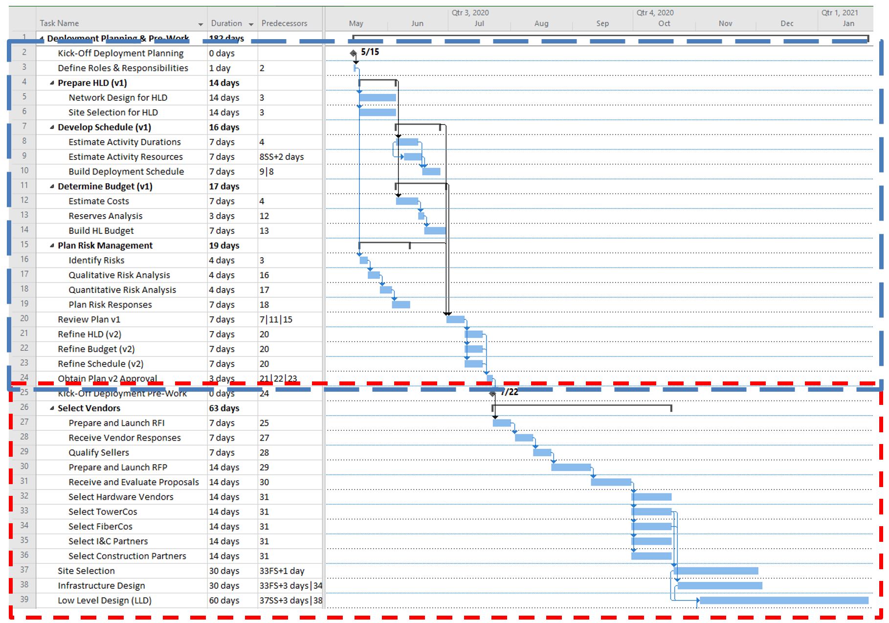
Figure 4. Gantt Chart for Deployment Planning & Pre-Work
In Figure 4, each row represents an activity. Then to the right, blue bars represent activity duration, black brackets represent summary activities, diamonds represent milestones, and arrows represent relationships. Figure 4 Illustrates the Deployment Planning (marked in blue) and Pre-work Phase (marked in red), with two internal iterations for the Project Plan (v1, and v2). It considers activities carried out in parallel by separate teams. Based on this chart:
Once the Planning stage is complete, Vendors are selected, and the first batch of Low-Level Designs (LLD) are ready, the operator may authorize the start of Deployment Execution. The purpose of the above analysis is to provide the NaaS operator an example of the Planning & Prework stage; however, duration of each phase depends on NaaS operator needs. The Gant Chart templates are provided for the NaaS Operator to customize their own tasks and schedule.
3.1.3 Deployment execution stage
Once the Pre-Work stage is complete, the NaaS Operator may authorize the start of Deployment Execution. Below the Gantt Chart for the Deployment Execution phase, showing how the last activities of the Pre-Work phase (Site Selection, Infrastructure Design, and LLD) partially overlap with Deployment Execution:
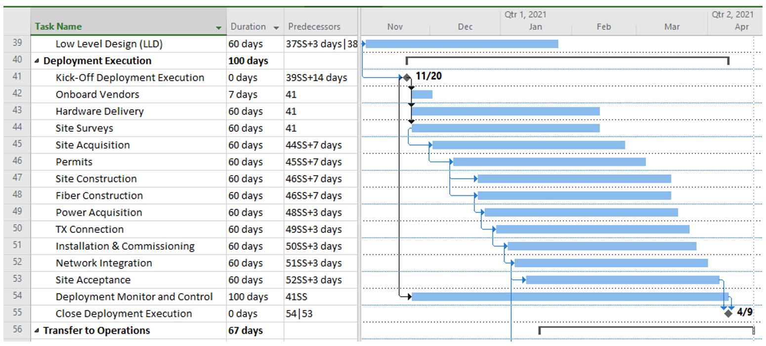
Figure 5. Gantt Chart for Deployment Execution
From the above chart:
The Deployment Manager must adjust the schedule according to the actual team for which the provided Gantt Chart templates can be used to customize its own schedule considering available resources for planning, volume of work needed to develop the HLD and LLD, and other external factors such as responses from pre-selected vendors and initial contact with local authorities for permits and licenses.
3.1.4 Deployment Closure and Transfer to Operations
After the first batch of sites has been deployed, and is now providing services to end users, this set enters the Transfer to Operations phase. During this phase, the main responsibility of the Deployment Manager is to confirm all work is done according to requirements, gain final acceptance of sites from the client stakeholder (e.g. the Operations group), complete final performance reporting, prepare historical records and gather final lessons learnt and update documentation for future projects.
Figure 6 shows a generic Gantt Chart for this phase:

Figure 6. Gantt Chart for Transfer to Operations
As with previous stages, a Gantt Chart Template is provided to the NaaS Operator for customization according to its own schedule, tasks and Team.
Gantt chart concepts presented in this and previous sections can be instantiated through Scheduling Tools such as Microsoft Project or Project Libre, where users can build a new project, add or remove activities, adjust their relationships, durations, and allocated resources. These tools allow the Deployment Manager to estimate project duration by using the Critical Path Method (CPM).
The Deployment Manager should calculate initial duration estimates to build the Schedule Baseline (Gantt Chart). Best practices introduce several estimation techniques which are presented and analyzed in the Primer on Critical Path Method & Estimation Techniques.
3.2 Resource Planning
Resource Planning describes the Human resources required to complete a deployment. To define a comprehensive Resource Plan, the NaaS operator must identify their required skills, quantify the amount of resources required for each job and develop a Work schedule for each resource within the project. The following roles can be considered for the NaaS Operator Deployment Phases:
Network -RAN/Transport/Core/IP
Operations – Deployment/Logistics/Maintenance
Financial / Legal – Leasing/Financing/RFP
This module assumes that dedicated resources for Construction activities will be provided by 3rd Party companies, however this will depend on NaaS operator Strategy.
Please note that the Runbook provides a customizable Resource Planning Template useful to Plan Human Resources Schedule, which the NaaS Operator may tailor to fit its Organizational needs, and schedule.
The following recommendations on Resource Planning are provided to the NaaS Operator to customize their own Resource Plan:
After the Deployment Manager has come up with a Resource Schedule, accurate estimates can be performed. During execution, this baseline can only be changed using formal change control procedures (see Section 4.3) and shall be used as the basis for comparison to actual results.
3.2.1 Resource Planning Best Practices
Often resources are shared among several projects or activities in the organization due cost effectiveness. Because of this, the resources originally considered for activities may not be available, or their commitment to project activities could be limited.
How the Deployment Manager manages these situations will be influenced by the overall project priority among others in the program of the organization. Examples of best practices in resource management include:
3.3 Cost Planning
Cost Planning describes the total quantity of financial resources required during each Deployment phase. The total cost of all labor, equipment and materials should be calculated, as well as the total cost of undertaking each activity within the deployment plan.
Typically, a Deployment Project spends most of the budget on purchasing, leasing, renting or contracting the resources for the project (e.g. Network Equipment, Power Equipment, Supporting Infra, Services, Labor). Categorizing the expenses in this way will help to easily identify a cost anomaly that affects the planned budget. Cost Breakdown Structure is used to analyze required Budget and facilitate the Cost Planning activities. This PlayBook provides a customizable Cost Breakdown Structure spreadsheet to reflect and analyze costs. For more information please see the Cost Breakdown Structure (CBS) Primer.
Depending on the NaaS Operator budget strategy and Deployment Manager Scope they can either receive a time-phased budget or elaborate the budget for NaaS operator organization analysis and approval. Once the Deployment Manager has estimated durations and costs for every activity and resource, the budget baseline can be built and either compared to the assigned budget or presented for approval.
3.4 Communications & Stakeholder Management
A Deployment project needs excellent communication as a critical component for success. Stakeholder management is a set of techniques that will ensure the right messages are sent, received, and understood by the right Stakeholders. It comprises three main steps:
Identify Stakeholders
The Deployment Manager should identify stakeholders and their roles within the deployment. Stakeholders are the employees within the NaaS organization (Internal Stakeholders) or other collaborators outside the organization such as vendors, contractors, customers, as they all have interests, roles and responsibilities in the Deployment project.
Define Roles & Responsibilities
A key tool to implement Stakeholder Management throughout the project lifecycle is a Responsibility Assignment Matrix (RAM), commonly known as RACI chart, as the one shown below:
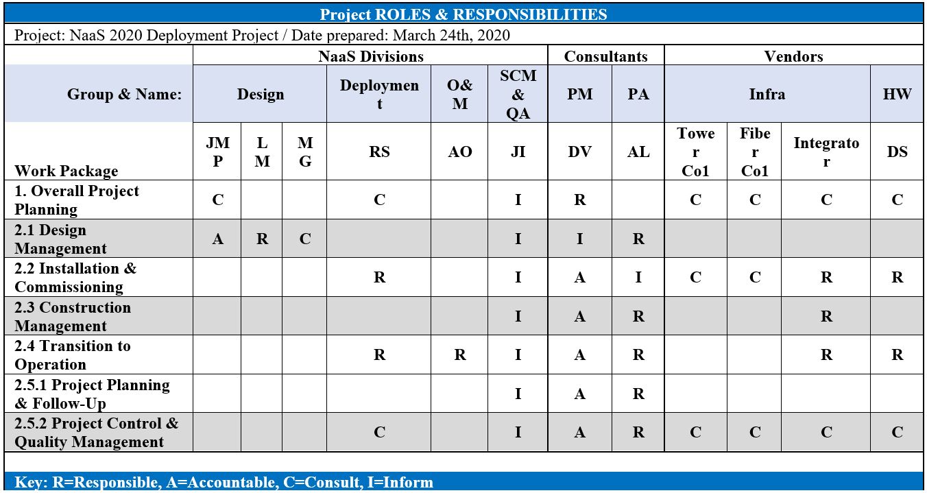
Table 3. Project Responsibility Assignment Matrix (RAM) or RACI Chart
From the table above, the roles are defined as:
With the help of this simple table, a large part of uncertainty of who is responsible of what will be avoided. Also, this prevents conflict and potential delays. Every project stakeholder shall have a clear understanding of what is their expected contribution levels, deliverables and deadlines.
This RACI matrix is provided as a template for customization by the NaaS Operator.
Develop Communication Strategy
Once stakeholders have been identified and their roles and responsibilities has been registered in the RACI matrix, it is possible to define a communication strategy by performing the next tasks:
3.5 Risk Planning
To ensure a successful deployment, a comprehensive analysis and planning for risks must be performed. Depending on the complexity of the deployment, the number of identified risks varies. The Deployment Manager can use a Risk Register to manage, control and create possible solutions. This document identifies all the foreseeable risks and the actions needed to prevent each risk for occurring
Risk planning is divided in 2 critical steps which are detailed in the following sections:
3.5.1 Identify Risks
It is imperative to identify Individual Risks, as well as general Project Risks, and document their characteristics. The Deployment Manager and NaaS operator key personnel may identify them through workshops that may include some form of brainstorming.
The goal of brainstorming is to obtain a comprehensive list of individual project risks sources of the overall project and assign each risk an owner. This means assigning to the right person that will apply the planned mitigation actions for a particular risk. Then a Qualitative Risk Analysis should be performed to assign a priority for each risk.
Each risk is assigned a category according to its impact and probability, which is then translated into a score that helps to prioritize the risks; for further additional analysis based on urgency, priority, impact. A generic matrix for priority scoring is shown below:
|
Probability |
|
|
|
|
|
|
|
0.1 |
|
|
|
|
|
|
|
0.3 |
|
|
|
|
|
|
|
0.5 |
|
|
|
|
|
|
|
0.7 |
|
|
|
|
|
|
|
0.9 |
|
|
|
|
|
|
|
|
0.1 |
0.3 |
0.5 |
0.7 |
0.9 |
Impact |
|
|
|
|
|
|
|
|
Table 4. Risk Priority Scoring Table
In addition, a quantitative risk analysis may be performed. For more information please refer to the Primer on Risk Analysis Techniques.
3.5.2 Plan Risk Responses
Once risks have been identified, and analyzed, plans should be developed by the nominated risk owner or the Deployment Manager to address every individual project risk. The NaaS Operator should also consider how to respond appropriately to the current level of overall project risk.
There are five alternative strategies to deal with risks:
As a result of identifying risks and planning responses, the team will generate a Risk Register, which is the document that captures all the details of the identified risks, individual and general to the project. A Risk Register Template aligned with the NaaS deployment scenario is shown in the following table, the NaaS operator may use it as a baseline and tailor it to its own deployment scenario by adding any other detected risks:
|
ID |
Cause |
Event |
Effect |
Prob. |
Priority |
EVM (USD) |
Strategy and Response Plan |
Risk Owner |
|
01 |
If the Target Coverage is changed |
The Site List will change |
Rework will be necessary |
0.1 |
Medium |
/ |
Ensure Coverage Area and Service Requirements Change is managed and signed by client. |
R.R. |
|
02 |
If the radio hardware delivered doesnt perform as advertised |
Radio Performance will be lower |
Configuration change or Hardware Change |
0.1 |
Low |
/ |
Ensure adequate testing and homologation procedures are followed |
J.M.P. |
|
03 |
If installation teams lack the necessary skills and training |
Installation will take longer or give way for more accidents or damages |
Delivery delays, fines, lawsuits |
0.3 |
Medium |
/ |
Ensure adequate training and certification for all personnel assigned to the project |
R.S. |
|
04 |
If the Operator loses the Deployment Permit |
The Deployment may be halted or cancelled |
Financial Loss, Loss of Revenue |
0.5 |
High |
100 M |
Secure Permit, and adhere to all regulation |
R.R. |
|
05 |
If engineers in the Design Team are unavailable |
HLD and LLD sections will not be worked on |
Project Delays |
0.7 |
High |
/ |
Synchronize with the Engineering Department on 06Resource Availab07ility, Resource Cal08endars, update Sched090ule if needed |
M.G. |
|
06 |
If actual costs are much higher than established margin off estimated costs |
Budget will not be enough to cover the Scope |
Activities in the critical path may take longer, quality may need to be reduced, or Scope reduced |
0.5 |
High |
75 M |
Obtain enough references for the 20% of concepts that count for 80% of the budget (Pareto Law). Carry out more testing, and widen Vendor Selection to foster competition. Practice Sole Source and Single Vendor avoidance. |
A.U. |
|
07 |
If key resources dedicated to critical path activities become unavailable (illness, resignation) |
Activities progress will stop while a replacement is found |
Project Delays, Cost increased, Quality Reduced |
0.1 |
Medium |
/ |
Establish Knowledge Transfer mechanisms, Handover process, and back-up team members |
M.G. |
|
08 |
If the organization suffers a cyberattack |
Project Data is lost completely |
Project activities must stop until systems and data can be rebuilt |
0.1 |
Medium |
10 M |
Follow IT Best Practices, Periodic Backups, promote Information Security regulations throughout the team and external stakeholders |
J.G. |
|
09 |
If a supplier goes out of business |
Activities related to the supplier stop, procurements with supplier are stopped, budget spent at stake |
Project Delays, financial loss, quality reduced |
0.1 |
Medium |
/ |
Establish sound Vendor Selection Criteria (e.g. Financial History, ongoing lawsuits, production capacity), and qualify alternative sellers ready to cover supply for emergencies. |
A.U. |
|
10 |
If the project or organization acquire civil responsibility for an accident |
Activities related to the accident must stop, government may revoke the license to operate |
Massive financial loss, delay, liability |
0.1 |
Medium |
80 M |
Establish mechanisms in contracts to isolate company from damage caused by third parties, and buy insurance policies. |
Y.G. |
|
11 |
If any financial resource is stolen by any stakeholder |
Activities related to that resource wont be completed |
Financial Loss, Activity Delays |
0.3 |
Low |
100 k |
Establish strong mechanisms for Budget Management, avoid cash transactions when possible |
S.R. |
|
12 |
If any tool or instrument is required but not available |
Activities related to this resource cant start, unless resource is acquired |
Activity Delays, Cost increase |
0.3 |
Medium |
/ |
Strengthen Resource Requirements planning, determine the need to buy or rent each tool or instrument |
R.S. |
|
13 |
If any hardware element of sites is vandalized or stolen |
Activities related to unfinished sites must stop until hardware is replaced; or finished sites become out of service |
Activity Delays, Cost Increase |
0.3 |
Medium |
8 M |
Evaluate mechanisms or anti-vandalism add-ons for high-priority sites (stronger locks, perimeters, alarms, cameras). Consider insurance policies. |
R.S. |
|
14 |
If site survey reveals a selected site lacks space, energy or transport capabilities |
Site cannot be built, installed or deployed |
Activity Delays, Cost Increase, Quality reduced |
0.1 |
Low |
/ |
Accept. Evaluate second alternatives for each site, consider more than one transport solution per site, and off-grid energy options |
X.H. |
|
15 |
If power is unstable on-site for construction, installation or commissioning work |
Site cannot be deployed reliably, resulting in additional site visits |
Activity Delays, Cost Increase, Quality Reduced |
0.9 |
High |
/ |
Mitigate. Evaluate usage of portable power generators for installation and construction work; and evaluate the need for higher availability and capacity Backup Power for key sites. |
J.V. |
Table 5. Generic Risk Register for the NaaS scenario
4 Deployment Control & Monitoring
The Deployment Control and Monitoring starts as soon as a project begins. It is the process of tracking, reviewing, and regulating the progress in order to meet the deployment objectives. Moreover, this process is majorly concerned with:
Control and Monitoring Deployment Phase is where the Deployment Manager role has the highest impact. He must measure actual performance against the performance baselines, to determine if variances warrant preventative actions, corrective actions or other change requests.
4.1 Control & Monitoring Guidelines
Control and Monitoring are essential for effective network deployment, from Network Design to a successful transfer to operations. The Deployment Manager should track all the tasks involved using methodologies and strategies that are already defined and planned before the execution.
In order to monitor work, the Deployment Manager shall lead the project team to gather Work Performance Data, such as reports, KPIs, and statistics often processed and summarized by a Deployment Management Tool. The following sections provide guidance to track specific tasks throughout the deployment process. Useful methods to analyze and track deployment performance are described in the Primer on Deployment Performance.
4.1.1 Tracking Design Tasks
Design for the NaaS scenario should be tracked at the site level. To this end, the Design Team should feed progress data into a shared tool or template which the Deployment Manager can monitor for current progress and deviations from the planned work. What has been found to be the most effective information to capture is the Date of completion for each major step in the design process.
This way, the Deployment Manager can obtain KPIs regarding efficiency and throughput of the Design Team. The PlayBook provides templates that the NaaS operator can use to record KPIs described in this section, please refer to the Deployment Tracking Worksheet.
Specially during Network Design, it is essential to track the generation of Low-Level Design (LLDs) and establish agreement with the Design team on delivery dates for batches of sites, that allow to kickstart deployment execution of the first sites.
Recommended KPIs to measure progress of Design tasks include:
Together, the Average Design Time per site (hrs) and the LLD Rework Rate (%) allow for a reasonable estimation of time for the design phase of the complete set of sites.
4.1.2 Tracking Deployment Execution Tasks
Now that partners are carrying out site surveys, building sites and towers, connecting power, raising and installing radio equipment, building fiber, commissioning and integrating equipment, the Deployment Manager has the responsibility for tracking how work is advancing with respect to the baselines. This tracking determines whether there are deviations, forecast updated deadlines and the need for preventive or corrective action.
In terms of Network Deployment, the Deployment Manager could track the volume of sites acquired, built, or integrated up to the current day, and how much was planned to be achieved by then; and also, how much has it cost so far.
To do this, a Deployment Tracking Worksheet is provided to the NaaS Operator for customization.
After extensive experience in Deployment projects, it has been found that storing the date for each milestone is enough to track each deployment step, because it allows to understand delays and advancement of steps at the site level, at the same time allowing for Data Analysis and Visualization.
Below is a sample of the Deployment Tracking Spreadsheet:
|
SiteID |
Region |
District |
SiteConfig |
TowerCo |
TowerID |
SiteDesignReady_BL |
SiteDesignReady_AC |
|
AA00219 |
North |
MTY |
MACRO |
SuperTowers |
ST0014 |
6/1/2020 |
6/5/2020 |
|
AA00951 |
North |
ZAC |
MINI |
PremiumTowers |
PT001211 |
6/1/2020 |
6/2/2020 |
|
ED00640 |
Center |
GTO |
SMALL |
NaaS Owned |
T00001 |
6/1/2020 |
6/4/2020 |
|
FE00941 |
Center |
QRO |
MACRO |
NaaS Owned |
T00013 |
6/1/2020 |
6/4/2020 |
|
VC00029 |
South |
VER |
MINI |
NeatTowers |
NT0041 |
6/1/2020 |
6/2/2020 |
|
CH00128 |
South |
CHI |
SMALL |
NeatTowers |
NT0111 |
6/1/2020 |
6/3/2020 |
|
CA00135 |
North |
MTY |
MACRO |
SuperTowers |
ST0524 |
6/1/2020 |
6/4/2020 |
|
CA00216 |
North |
ZAC |
MINI |
PremiumTowers |
PT044331 |
6/8/2020 |
6/11/2020 |
|
CA00162 |
Center |
GTO |
SMALL |
NaaS Owned |
T01110 |
6/8/2020 |
6/12/2020 |
|
CA00257 |
Center |
QRO |
MACRO |
NaaS Owned |
T00054 |
6/8/2020 |
6/10/2020 |
|
CA00391 |
South |
VER |
MINI |
SuperTowers |
ST0756 |
6/8/2020 |
6/13/2020 |
|
CA00130 |
South |
CHI |
SMALL |
PremiumTowers |
PT00984 |
6/8/2020 |
6/11/2020 |
|
CA00149 |
North |
MTY |
MACRO |
NaaS Owned |
T00612 |
6/8/2020 |
6/9/2020 |
|
CA00199 |
North |
ZAC |
MINI |
NaaS Owned |
T00803 |
6/8/2020 |
6/9/2020 |
|
CA00260 |
Center |
GTO |
SMALL |
NeatTowers |
NT00454 |
6/8/2020 |
6/12/2020 |
|
CA00261 |
Center |
QRO |
MACRO |
SuperTowers |
ST3123 |
6/8/2020 |
6/11/2020 |
|
CA00262 |
South |
VER |
MINI |
PremiumTowers |
PT99231 |
6/15/2020 |
6/16/2020 |
Table 7. Sample Deployment Tracking Spreadsheet
From the above:
During planning, the team records the planned dates in the columns with the BL (baseline) identifier. Then, during execution the same team records the actual dates in columns with the AD identifier. Further Milestones become recorded in the remaining columns to the right, as shown below:
|
SiteID |
SiteDesignReady_BL |
SiteDesignReady_AD |
ReadyForCW_BL |
ReadyForCW_AD |
|
AA00219 |
6/1/2020 |
6/5/2020 |
6/13/2020 |
6/14/2020 |
|
AA00951 |
6/1/2020 |
6/2/2020 |
6/13/2020 |
6/16/2020 |
|
ED00640 |
6/1/2020 |
6/4/2020 |
6/13/2020 |
6/17/2020 |
|
FE00941 |
6/1/2020 |
6/4/2020 |
6/13/2020 |
6/17/2020 |
|
VC00029 |
6/1/2020 |
6/2/2020 |
6/13/2020 |
6/17/2020 |
|
CH00128 |
6/1/2020 |
6/3/2020 |
6/13/2020 |
6/17/2020 |
|
CA00135 |
6/1/2020 |
6/4/2020 |
6/13/2020 |
6/17/2020 |
|
CA00216 |
6/8/2020 |
6/11/2020 |
6/20/2020 |
6/22/2020 |
|
CA00162 |
6/8/2020 |
6/12/2020 |
6/20/2020 |
6/22/2020 |
|
CA00257 |
6/8/2020 |
6/10/2020 |
6/20/2020 |
6/24/2020 |
|
CA00391 |
6/8/2020 |
6/13/2020 |
6/20/2020 |
6/22/2020 |
|
CA00130 |
6/8/2020 |
6/11/2020 |
6/20/2020 |
6/25/2020 |
|
CA00149 |
6/8/2020 |
6/9/2020 |
6/20/2020 |
6/21/2020 |
|
CA00199 |
6/8/2020 |
6/9/2020 |
6/20/2020 |
6/24/2020 |
|
CA00260 |
6/8/2020 |
6/12/2020 |
6/20/2020 |
6/21/2020 |
Table 8. Sample Deployment Tracking Spreadsheet (continued)
Once the baseline dates are established for each site, they are shown on a week-by-week basis. A fragment of the summary sheet is shown below:
|
Deployment Tracking Summary |
|
|
|
|
|||
|
Year |
Week |
StartDate |
EndDate |
SiteDesignReady _BL |
SiteDesignReady _BL(SUM) |
SiteDesignReady _AD |
SiteDesignReady _AD(SUM) |
|
2020 |
22 |
5/25/2020 |
5/31/2020 |
– |
– |
– |
– |
|
2020 |
23 |
6/1/2020 |
6/7/2020 |
7 |
7 |
7 |
7 |
|
2020 |
24 |
6/8/2020 |
6/14/2020 |
9 |
16 |
9 |
16 |
|
2020 |
25 |
6/15/2020 |
6/21/2020 |
22 |
38 |
11 |
27 |
|
2020 |
26 |
6/22/2020 |
6/28/2020 |
13 |
51 |
13 |
40 |
|
2020 |
27 |
6/29/2020 |
7/5/2020 |
16 |
67 |
26 |
66 |
|
2020 |
28 |
7/6/2020 |
7/12/2020 |
19 |
86 |
19 |
85 |
|
2020 |
29 |
7/13/2020 |
7/19/2020 |
14 |
100 |
14 |
99 |
|
2020 |
30 |
7/20/2020 |
7/26/2020 |
– |
100 |
1 |
100 |
|
2020 |
31 |
7/27/2020 |
8/2/2020 |
– |
100 |
– |
100 |
|
2020 |
32 |
8/3/2020 |
8/9/2020 |
– |
100 |
– |
100 |
Table 9. Deployment Tracking Summary sheet
From the above table:
The PlayBook provides the NaaS operator useful customizable templates to create their own charts depending on the deployment needs, please refer to the Site Tracking Sheet included in the Deployment Tracking Worksheet.
In order to illustrate and compare the performance of the project with respect to the baseline, it’s possible to show the Actual Schedule graphic and the Baseline Schedule graphic, for each milestone. Below, is the SiteDesignReady Baseline Chart vs an Actual Simulation:
Figure 12. Baseline vs Actual for the Site Design Ready Milestone chart
From the above chart, from week 23 to week 24, the actual performance matched that of the baseline. Then, on week 25 the performance suffered, delivering only 27 designs of the 38 planned. The performance lagged during week 26, but at week 27 the gap was almost eliminated. By week 28 and 29, the difference was compensated, and the project work recovered soon enough.
Some of the recommended KPIs to track during Deployment Execution include:
Also, for a finer understanding of the work dynamic among Deployment Milestones, its possible calculate the Minimum, Maximum, and Average of:
Please refer to Deployment KPIs within Deployment Tracking Worksheet to find a useful spreadsheet that NaaS operator use to track deployment.
4.1.3 Tracking Transfer to Operations Tasks
Tracking Transfer to operation Process is needed to track the adequate progress of the site reception by operations. Smooth transition allows the release Deployment Execution resources to handle the next batch of sites for integration.
After integration, Transfer to Operations includes a period of Incidences Babysitting. The Deployment Manager should be aware of the total number of incidents during the babysitting process, and the time it took to resolve them. Unless these are within acceptable levels, it could be an evidence of faulty delivery, or further training needs for the Operations group.
Once the site has been accepted by Operations, the Deployment Manager also must gather the lessons learned, and release the resources no longer needed for the project.
The closure of the deployment project involves closing work packages, making sure invoices have been managed, and payments to suppliers sent by Supply Chain Management.
The recommended KPIs to track Transfer to Operations include:
Please refer to Deployment KPIs within Deployment Tracking Worksheet where NaaS Operator can find the functional spreadsheet for use during the Transfer to Operations phase.
4.2 Risk Management
By accurately tracking deployment processes, the Deployment Manager is better equipped to detect deviations or anomalies that may be related to previously identified risks during planning, or risks that hadnt been unveiled during the planning phases.
Risk Management is an on-going activity for the Deployment Manager, consisting of the following tasks which are performed taking the Risk Register developed during planning as a starting point:
4.2.1 Track Identified Risks
The Deployment Manager can use the Risk Register provided to track the overall risks. As the deployment progresses, risks change: probability, impact, priority and even response plans may change.
Thus, the Deployment managers must work with the risk owners to update trigger conditions and the related metrics in the Risk Register.
4.2.2 Identify and Analyze New Risks
The Deployment Manager periodically works with key stakeholders and risk owners to identify new risks. What is new? What has changed? What has been overlooked?
In particular, the following aspects shall be considered to identify new risks:
4.2.3 Manage Risk Response Plans
For each risk or set of risks, a response has been planned. As detailed in section 3.5, Risk owners are responsible to execute the plans. The Deployment Manager must ensure that Response Plans are triggered and implemented at the most appropriate time.
The Deployment Manager continues to work with the risk owners to evaluate the effectiveness of the responses throughout the Deployment Process. Responses are modified as needed and updated in the Risk Register.
4.3 Change Management
NaaS Operator must understand Change within the context of Deployment Management as anything that transforms or impacts projects, tasks, processes, structures, or even job functions.
Therefore, Change Management is critical to effectively adapt the plans, tasks and outcomes of the deployment process. The Deployment Manager must manage change in an effective way to minimize the impact or leverage the change and maintain consistency across the NaaS organization
A communication strategy is the key to achieve a successful implementation of change. As soon as it is detected that a change will be required, a communication channel must be opened between the Deployment Manager and the affected stakeholders. This section analyzes techniques to document, examine, decide, communicate, and implement changes that will help NaaS operator take effective actions over unplanned issues.
4.3.1 Change Control Procedure
Change Control is about dealing with issues, which could be requests for change, off-specification and concerns/problems (other).
To manage change, every Change Request (and its related impact on Schedule/Cost/Quality/Scope) shall be reviewed and approved by an appointed Change Authority. Only approved changes may be implemented. The Change Authority is a person or group who considers requests for change and off-specifications. Commonly is the responsibility of the Deployment Manager but it can also be the Executive Team, Board of Directors, a Change Committee or a specific member of the NaaS Organization.
For a better understanding this section analyze a common change that may happen in RAN LLD.
Change Example: A Change in RAN LLD
In this hypothetical scenario the NaaS Operator share the same tower and masts with another operator. Even when site survey indicates that there is enough space in mast to install the antenna, the Installation Engineer notice that required Azimuth mismatch with space availability. There are 5 steps to help Deployment manager handle unexpected Issues and Changes: Capture, Examine, Propose, Decide, and Implement.
In the example the issue is a Request of change the Azimuth must be changed to one that fits space limitations. The Deployment Manager record this new Issue as Request Change in the Issue Register and in the Design Tracker as a new Iteration including the Change Description.
In the example is a Must Have, the Azimuth must be adapted to space limitations.
In the example one of the proposals may be an LLD redesign that includes an Azimuth shift in the other sectors in order to avoid an overlap.
In the example it is assumed that the Designer is available at the time, there are no other installation task that depend on the antenna installation; thus, the original schedule is not affected and the change in the cost plan is within the contingency reserve. The Deployment Manager can authorize the required change.
In the Example the Deployment Manager must inform Designer of the redesign requirements clearly with all the new updates of the site. Field Technician must be informed to postpone antenna installation work until the redesign is ready and continue with missing tasks. The Deployment Manager records the Issue closure date in the Issue Register once is solved.
Figure 13 is a graphical representation of the Issue and change Control Procedure
Figure 13 Issue and Change Control Procedure
4.3.2 Dealing with Project Issues
Issue is a relevant event that has happened and that requires some management action (for example, a question or a Change Request). Issues can be raised at any time during the project and by anyone. Identified risks that are materialized, or the response to those risks when implemented, can be considered issues under the change management context.
There are 3 types of Issues:
Request for Change: It is a proposal for a change to a baselined Design, Schedule, Specification, Work Guideline that has already been approved. i.e. This could be a design change, Installation methods of procedures updates.
Off-Specification: This is something that was agreed to be done but is not provided by the supplier and/or not forecast to be provided, and therefore, is out of specification or off-specification.
Problem/Concern: which could also be a question (positive or negative): Any other issue that the Deployment Manager needs to resolve or escalate; this could be positive or negative.
Figure 14 Dealing with Deployment Issues
As shown in Figure 14, the Deployment Manager and Change authority deal with changes depending on which kind of issue is facing, the strategy also considers the impact of the issue that will decide if the Deployment manager can manage the issue by himself or escalate it to the Change Authority. Below there are some examples of dealing with issues in change management:
Once the process is defined, the Deployment Manager decides which tools he will use to manage that change control process. Many teams turn to simple issue register spreadsheets to list change requests and track progress. Typically, there are several data points to manage within a change control process:
Table 13 is a Sample of the Spreadsheet described above:

Table 13 Sample of Issue Register
4.3.3 Change Management Best Practices
The absence of proper communication for a change process may turn into a failed implementation of the required change. Overcommunication or no communication are both undesirable as due to this the whole effort of change can be derailed. If communication is made efficiently and clearly, it will help in building awareness and in getting the subsequent support in the entire deployment.
Below are some items that the Deployment Manager should consider as best practices:
1. Site Survey Introduction
A Site Survey is the process of collecting data from an existing site or new area before the deployment of Network Equipment takes place. Site Survey is done through a physical visit to the desired location by a team that will collect the most relevant data according to the NaaS Deployment requirements. A Site Survey is required to evaluate whether the selected site is suitable for construction/adaptation of a Radio/Transport site, and to validate that it fulfills both design and construction criteria.
The Site Survey module provides the NaaS Operator with strategic guidelines that serve as a reference point to decide when a Site Survey is required and which is the best approach to carry it out based on NaaS deployment requirements and use cases.
Finally, through the use of this module, NaaS Operators will be able to generate a comprehensive and complete Site Survey Report, which will be leveraged by Site Construction Management and Network Design modules to adapt network requirements based on it.
1.1 Module Objectives
This module will enable a NaaS Operator to carry out Site Survey activities for different use cases. The specific objectives of this module are to:
1.2 Module Framework
The NaaS PlayBook Framework shown in Figure 1 displays the PlayBook Modules and their relationship to the Site Survey Module.
Strategic Plan & Scope and High-Level Network Architecture drive the strategic decisions to forthcoming phases. Deployment is the second step in the implementation strategy, and as other modules, it is supported by Supply Chain Management.
The Site Survey module is included within the Deployment stream and its target is to gather the most relevant data from existing sites, or new areas before the development of new sites takes place. The generated output from this module will be used by Site Construction Management and Network Design modules in order to have a clear image of the existing conditions and accordingly adapt site infrastructure and network design.
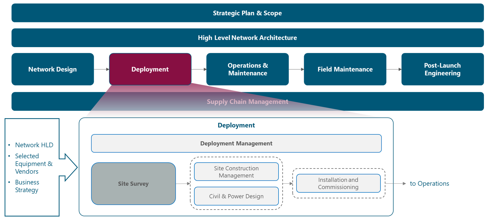
Figure 1. Module Framework.
Figure 2 presents a functional view of the Site Survey module where the main functional components are exhibited. Process overview together with critical module inputs are further described and examined in section 2.1.
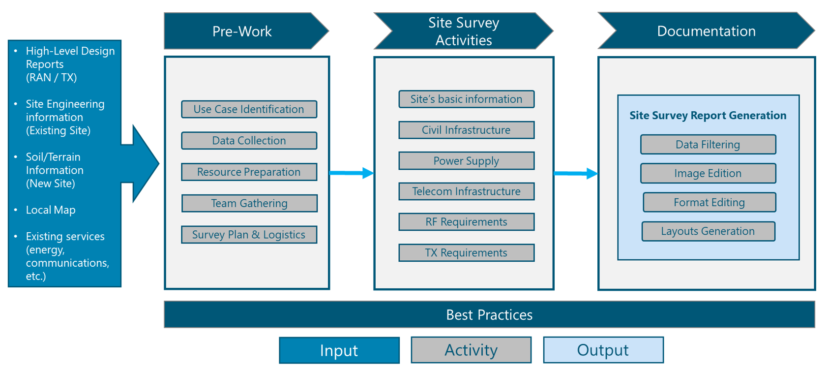
Figure 2. Site Survey Module Functional view.
The rest of the module is structured in three sections. Section 2 is a birds-eye view of the Site Survey process fundamentals. Section 3 provides guidelines to define a Site Survey strategy, identifying the site surveys and establishing policies for execution. Section 4 provides instructions and recommendations for the execution of the Site Survey activities finalizing with the customization of the Site Survey Report Template to match with the NaaS Operator deployment use cases.
2 Site Survey Fundamentals
This section presents a general overview of the Site Survey process, its importance in a NaaS Deployment and possible use cases in which it can be applied.
2.1 Process Overview
A Site Survey is the examination and data collection of a location which has been proposed to deploy a NaaS network site. This location can be an existing site or area in which a new site is intended to be built.
Site survey process is composed by two general subprocesses:
Table 1 describes main inputs required to define the Site Survey process and main activities.
|
Input |
Description |
Impact |
|
Local Map |
An updated map of the region in which the surveying sites are located. |
An updated map of the region is sometimes more useful than information from Google Earth. This is required to accurately locate the sites in the region. |
|
Existing Services in the region (energy, communications, etc.) |
Information about existing power and telecom services in the region. |
Site Survey responsible must be aware of the current state of the location before visiting it. |
|
Site Engineering Information |
Engineering layout of the existing construction and structures on a site. |
For existing sites, construction experts of the site survey team must be aware of existing buildings and/or structures to facilitate the survey. |
|
High-Level Design (HLD) Reports (RAN / TX) |
Proposed RF configuration and TX solutions to be deployed on a proposed location. |
Site survey team must collect relevant information of the proposed location for it to be evaluated. |
Table 1. Site Survey Module Input Data.
Main output of the Site Survey Module is the Site Survey Report (SSR) which contains all relevant information and photographic evidence to be used as a base for the evaluation of the location by the Site Construction and the Civil & Power Design modules. In addition, the SSR can be used as a feedback of the HLD reports. If proposed solutions dont match with the site’s requirement or if a new site is to be considered, the design team must apply the required changes based on the SSR.
2.2 Role of Site Survey in NaaS Deployment
Site Surveying is an important step in the deployment of a network as it provides exact insight into the current state of the proposed location. Site Survey report is a compilation of evidence that shall be analyzed in further steps to ensure that the proposed solutions (construction, RF and/or TX solutions) will fit with the current state of the facility/site.
A site survey will serve as the foundations for a solid site deployment as the survey team will collect important information about the current status of the site; from how to access the location and its layout, to how existing equipment is installed at the site and available space and infrastructure for the installation of new equipment.
A site survey shall provide enough information to develop plans and designs which match with the current state of the site, allowing NaaS Operators to save time and resources by dealing with accurate information. If a site survey is not carried out, the NaaS Operator deployment team may end up with an unfeasible design or deployment plan, having to consume extra time and resources in a rework process which may lead in deployment delays and the consequences that this entails.
2.3 Use Cases Review
Depending on the NaaS deployment requirements, a site survey can be used for different scenarios (use cases). Each use case will require the site survey to focus on specific details and collect specific data about the surveyed location. Table 2 describes possible use cases for a site survey process.
|
Use Case |
Description |
Survey Requirements |
|
Greenfield Deployment New Tower |
This scenario refers to a location which has no civil/tower infrastructure (and hence no telecom equipment). NaaS Deployment will evaluate the construction of a new site from the ground up in this location. |
● Survey of the location and any existing element such as a fence. ● How to access it. ● Elements that surround it. ● Terrain surface. ● Available power supply on site. |
|
Existing Tower No Overlay |
Deployment of a site in a location which has an existing tower that can be used for a new base station. |
● Requirements from previous use case, except for terrain surface ● Survey of tower characteristics and available space for equipment. ● Existing power equipment available capacity. ● Existing telecom infrastructure. ● Surroundings at tower level. ● Evidence for the evaluation of proposed TX solution. |
|
Existing Tower – Overlay |
Deployment of a site reusing the Radio equipment (antennas and/or radio units) which are already operating on the location. |
● Requirements from previous use case. ● Current locations, connections, and models of installed equipment. |
|
Greenfield Deployment Rooftop |
Deployment of a new site on top of a building. |
● Rooftop characteristics available space for construction. ● How to access the building and the rooftop. ● Elements surrounding the building. ● Rooftop surface. ● Available power supply on site. |
|
Existing Rooftop |
Deployment on an existing site located on a rooftop. |
● Requirements from previous use case. ● Antenna mounting structure characteristics and available space for equipment. ● Existing power equipment available capacity ● Existing telecom infrastructure. ● Evidence for the evaluation of proposed TX solution. |
Table 2. Site Survey use cases.
3 Site Survey Strategy Definition
This section presents guidelines for the definition of rules that will influence the overall Site Survey process based on NaaS deployment characteristics.
3.1 Site Survey Policy
Site Survey is a time-consuming process that implies an additional financial investment in the NaaS Deployment. For these reasons, NaaS Operators must establish some policies to help it decide which situations may trigger a Site Survey process. These situations will imply specific conditions and requirements that will govern the execution of the site survey process and specific activities.
NaaS Operator may use Table 3 as a base to define its own site survey policies:
|
Policy |
Description |
|
|
Remote Locations |
When the site is located on a remote and difficult to access location, NaaS Operators may evaluate if starting a site survey on that site is cost/time feasible to be carried out.
However, the use case shall be considered in this situation as follows:
● New Tower It is recommended to perform a site survey to get the site’s basic information (as descripted in section 4.2.1 and 4.2.2).
● Existing Tower Site Survey may not be required if enough documentation such as site/tower engineering plans are available.
This documentation must display detailed information about all existing infrastructure: towers, buildings, equipment rooms, etc. Documentation must also include (if applicable) detailed sketch of radio and transport equipment deployed on the tower: heights, orientations, tilts, etc. |
|
|
Previously done Site Surveys |
Site Survey reports may be available from a previous process. NaaS Operators may define whether previously done Site Survey reports are valid and can be relied on based on their generation date, who elaborated it, etc. |
|
|
Priority |
Based on NaaS deployment schedule, some locations may be considered prior to others. The less priority locations may not require a Site Survey to be done. |
Table 3. Site Survey policies examples.
In addition, sometimes GIS applications (like Google Street view) can help NaaS Operators in making a quick site survey without a visit to the location. However, NaaS Operators must evaluate the use of these applications for site surveying. Table 4 can help in this evaluation by displaying main pros and cons of using Google applications for site surveying.
|
Pros |
Cons |
|
● Can avoid visiting the location, which means time and cost savings for the NaaS Operator. ● Information about existing radio configurations (number of sectors) can be obtained. |
● No accurate details can be obtained (towers height, exact dimensions of the location, etc.) ● Details about equipment inside the location and installation details such as power sources, cabinets, cables, etc. may not be obtained. ● Data on Google applications may be outdated (picture available on the street view may have been taken some years ago) making any information obtained from it not reliable. |
Table 4. Google applications main pros and cons for site surveying.
Considering Table 4, it is recommended to use Google applications for site surveying only as a complement to other data. For instance, if an existing site is located in a remote location but the NaaS Operator has access to the engineering documentation of the site, then Google Street view can be used to obtain additional information, avoiding a visit to the location.
Table 5 displays site survey triggers examples, their description and required input data for each one.
|
Trigger |
Description |
Required Input Data |
|
Site Acquisition |
Before the acquisition of a location (whether for the construction of the whole infrastructure or to reutilize any existing infrastructure), a site survey is required to evaluate if the location is feasible for a base station. |
● Local Map |
|
Site Construction |
A site survey is required before the construction of a new site to develop a construction plan which matches with de NaaS deployment requirements. |
● Local Map ● Existing Services in the region (energy, communications, etc.) ● Site Engineering Information |
|
Site Modification |
Site survey is required to obtain information of an existing site and which modifications to its infrastructure must be done to deploy an overlay configuration. |
● Local Map ● Existing Services in the region (energy, communications, etc.) ● Site Engineering Information |
|
Design Solutions Validation |
Once High-Level designs (RF and TX) have been done, a site survey is required to obtain information that will be used for the feasibility evaluation of the proposed designs; whether for Greenfield or Overlay deployments. |
● Local Map ● Existing Services in the region (energy, communications, etc.) ● Site Engineering Information ● HLD Reports (RAN / TX) |
Table 5. Site Survey triggers.
3.2 Resources and Logistics
This section provides an overview of the required resources (human and material) involved in a Site Survey process. In addition, guidelines are given on how to organize survey teams and schedule the site survey activities.
3.2.1 Sourcing
Site survey activities require a certain amount of personnel, as well as hours / days of work. The NaaS Operator can choose between to different approaches to carry out the site survey activities:
The choice between in-sourcing or out-sourcing depends on several factors such as the number of resources that the NaaS Operator has, its financial capacity to contract a third-party and the presence of third-party companies experienced in site surveys in the region.
The NaaS Operator can carry out a cost evaluation considering the cost of each one of the human resources that would be assigned to the site survey activities (as will be discussed in section 3.2.2) and comparing this result with the cost of hiring a third-party company. NaaS Operators can evaluate which one (in-sourcing or out-sourcing) comes at a lower cost. Figure 3 represents a methodology that the NaaS Operator can use for the selection.
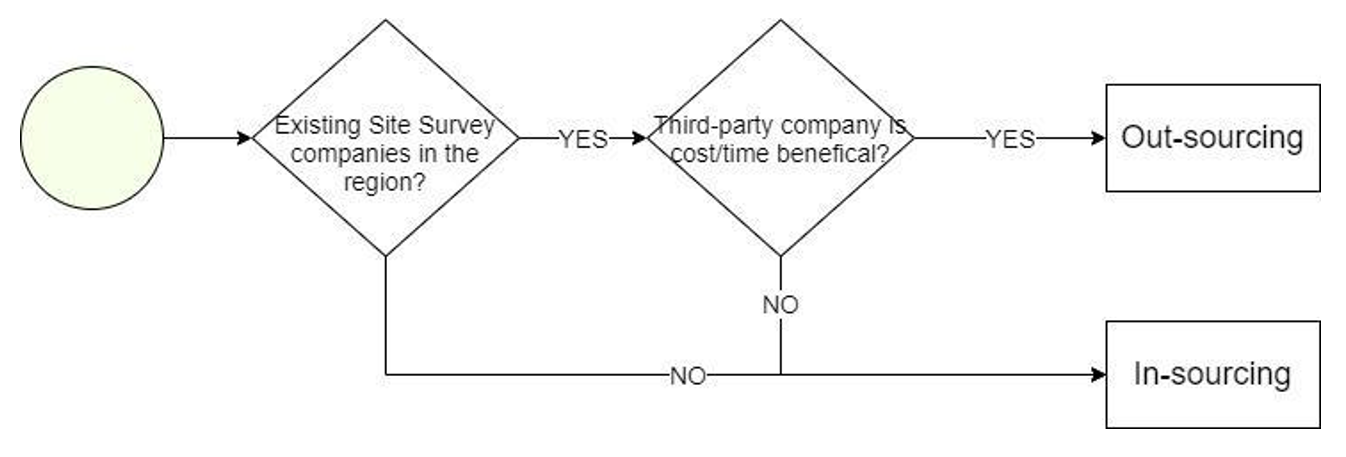
Figure 3. Sourcing definition process.
3.2.2 Team Composition & Material Description
This section will present requirements to establish an optimal team for Site Survey Activities and a description of materials required for such activities.
3.2.2.1 Team Composition
Site survey is a set of tasks involving various areas: civil infrastructure and installations inspections, and in some cases, tower climbing. Therefore, the integration of specialized personnel in such areas is necessary to carry out the required activities. The number and specialization of the personnel will depend on the use case for which the site survey will be used. For instance, it may be possible that a well-trained engineer can perform more than one of the site survey activities. However, it is recommended, for safety reasons, that at least two engineers per site to carry out the site survey activities.
Table 6 shows the required staff for the site survey and in which cases their participation is necessary:
|
Required Skills |
Description of activities |
Use cases |
|
RF Engineer |
Check that there are no major obstructions not observable during Design Process and evaluate compliance with RF requirements. |
● Recommended for all Use cases. Optional for Greenfield Towers |
|
TX Engineer |
Confirm that antenna location space satisfies MW requirements and validate MW LOS. May be necessary a tower climbing specialist. |
● Whenever a MW solution is to be deployed |
|
Civil Work specialist |
Document the state of the site: structure, foundations, existing buildings and/or towers, etc. |
● All use cases. |
|
Tower climbing specialist |
If equipment is installed on top of a tower, it is highly recommended to a person who can climb the tower and document the required data. Not every person can climb a tower. It requires a special certification to do so. One alternative to a certified specialist is to use a drone equipped with a camera if detailed data is not required for this task. |
● Existing Tower scenarios. ● Overlay scenario. |
Table 6. Site survey staff and description of activities.
The number of human resources required to conform each site survey will depend on the number of surveying sites, the personnel available in the organization, and the deployment times (schedule). More details on the formation of the teams will be given in section 4.1.4.
3.2.2.2 Required Materials
To carry out the documentation and measurement activities during the site survey, site survey team needs certain tools. Table 7 displays a list of the required materials and their use based on use cases.


Table 7. Required site survey materials and use cases.
3.2.3 Site Survey Tools
There are some tools and applications NaaS Operator can use to facilitate the organization and management before and during the site survey activities. These tools can be classified into three categories:
4 Site Survey Process Analysis and Customization
Figure 4 displays a generic end-to-end process to perform a Site Survey for a NaaS Deployment.
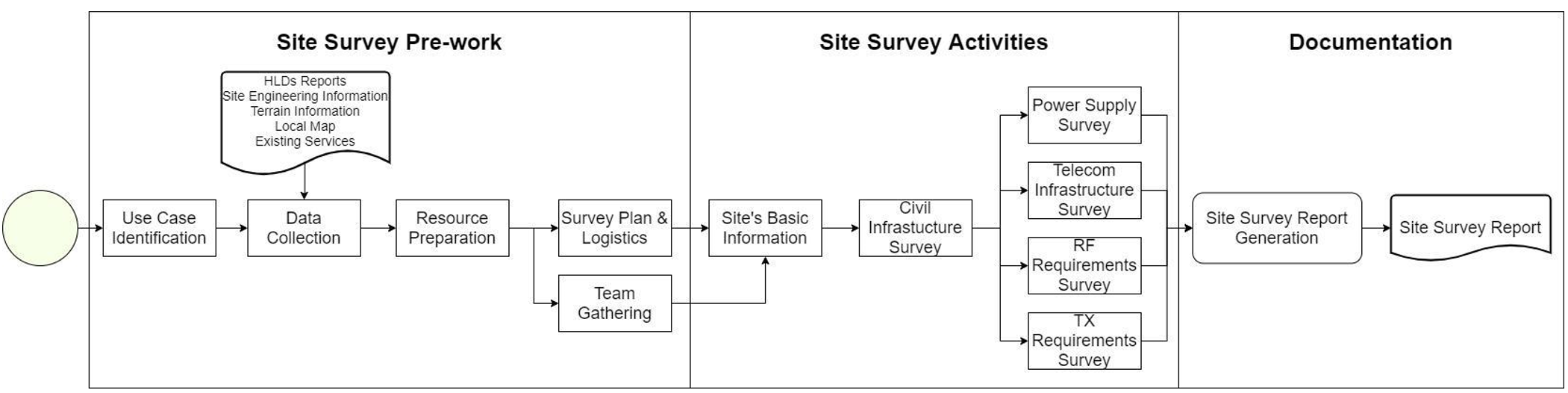
Figure 4. Site Survey process description.
Process starts by identifying the applicable use case for the specific site. Data Collection deals with the consolidation of required data provided as input documentation. Based on the identified use case, Resource Preparation defines the composition of the Site Survey team and required material to perform the site survey activities. Survey Plan & Logistics guides the team for internal organization and survey planning. Team Gathering assigns resources to the site survey teams based on the required team composition.
Site Survey activities start with Sites Basic Information which consists of the collection of basic details once the team arrives at the desired location. Civil Infrastructure Survey is performed to gather information regarding the site’s current structure. Power Supply Survey is done to capture data about elements that energize sites equipment. Telecom Infrastructure Survey is then carried out to illustrate existing telecom infrastructure such as cabinets, racks, and cabling. Then, RF Survey and TX Survey are made to obtain data to be used in the evaluation of the proposed HLD configurations. Finally, Site Survey Report Generation guides the creation of the SSR.
4.1 Site Survey Pre-Work
This section presents guidelines to establish and perform Site Survey preparation activities under the specific NaaS Operator environment and use cases.
4.1.1 Use Case Identification
Specific use case(s) can be identified based on the available input data and NaaS Deployment characteristics. This may lead to having more than one use case for a single location. For instance, two use cases can apply for a site with an existing tower: no overlay deployment and rooftop use cases. Therefore, the NaaS deployment may be composed of a combination of locations with different use cases each.
Each site in the NaaS deployment shall be matched (based on its own initial conditions) with its corresponding use case as shown in Table 2.
Final selection of the possible use cases shall be done by analyzing the available inputs. For instance, if no HLD is available, then it is not required the evaluation of RF and TX solutions, this will eliminate the existing tower and overlay use cases from consideration.
4.1.2 Data Collection
Site survey team must collect basic information about the locations and consolidate them into a single document which shall serve as a starting point in the planning definition.
Main data to be collected is displayed in Table 8.
|
Input |
Required data |
|
Local Map |
● Exact location (street name, number, etc.) |
|
Existing Services in the region (energy, communications, etc.) |
● Existing services on site |
|
Site Engineering Information |
● Existing infrastructure and buildings |
|
High-Level Design (HLD) Reports (RAN / TX) |
● Coordinates ● Microwave Path ● Configurations ● Scenario (Greenfield or Overlay) |
Table 8. Basic information to be collected.
NaaS Operators can use the Site Consolidated Information Template to create its own version of the consolidated information.
4.1.3 Resource Preparation
Based on the defined use case, NaaS Operators will be able to identify the required resources that will integrate the surveying team as discussed in section 3.2.2.1.
NaaS Operators can use the Site Survey Resources Checklist Template to identify its required resources based on the defined use case.
4.1.4 Team Gathering
Once the use case has been defined and the NaaS Operator is aware of which specialists are required to conform the site survey teams, it must select the right personnel among its organization to conform the teams. Table 9 can help NaaS Operator in the selection based on optimal qualifications required for each activity.
|
Required Site Survey Staff |
Qualifications |
|
Civil work specialist. |
● Knowledge and experience in civil engineering. ● Experience in field measurement and field data collection. ● Experience in base station construction (site foundations, towers construction, equipment room requirements). ● Experience in power systems for base stations. ● Experience in the installation of telecom equipment. |
|
RF Engineer |
● General knowledge in RF design ● Familiarized with RF components of a base station. ● Knowledge in the basic components of a base station, its installation and configuration: Baseband units, radio units and antennas. |
|
TX Engineer |
● General knowledge in TX design ● Familiarized with TX components of a base station. ● Knowledge in the basic components of a base station, its installation and configuration: Baseband units, radio units and antennas. |
|
Tower climbing specialist (in case of tower > 10 m) 1 |
● Valid and updated tower climbing certification (may vary from one country to another). ● Experience in base station deployments. |
|
1 NaaS Operator may require hiring external personal for this position. |
|
Table 9. Site Survey team members selection.
4.1.5 Survey Plan & Logistics
NaaS Operators must be aware that the site survey is a process that consumes a significant amount of time; as a general rule, it is considered that a site survey for one location requires one day. A proper project planning must be done for time and resource optimization.
The project planning may start by dividing the NaaS deployment overall region in smaller subregions if the sites are distributed along several regions. Each subregion will contain a certain amount of survey sites. NaaS Operators can then assign each region to a Site Survey team to document all sites in that specific subregion. In this way, survey teams can be easily coordinated, and a NaaS Operator can have control of the surveyed sites.
Creation of subregions and number of sites per subregion will depend on the distance between sites and NaaS deployment schedule. This means that a tradeoff exists between the number of subregions defined and deployment schedule: the more subregions defined; the more site survey teams will be required but the time to complete all Site Surveys can be reduced.
NaaS Operators must consider assigning priorities to each location. Priority can be defined based on Site Survey policies. For instance, site surveys triggered by a site acquisition process may be assigned a higher priority in the schedule as those locations may require the site survey activities to be performed in order to start the acquisition process.
Figure 5 displays an example of a 7 locations deployment.

Figure 5. Example of region with 7 locations.
Two possible situations can be defined of the survey plan of the example region:
- Based on distance between locations, three subregions can be defined as shown in Figure 6. This will require three site survey teams and three days of site survey activities.
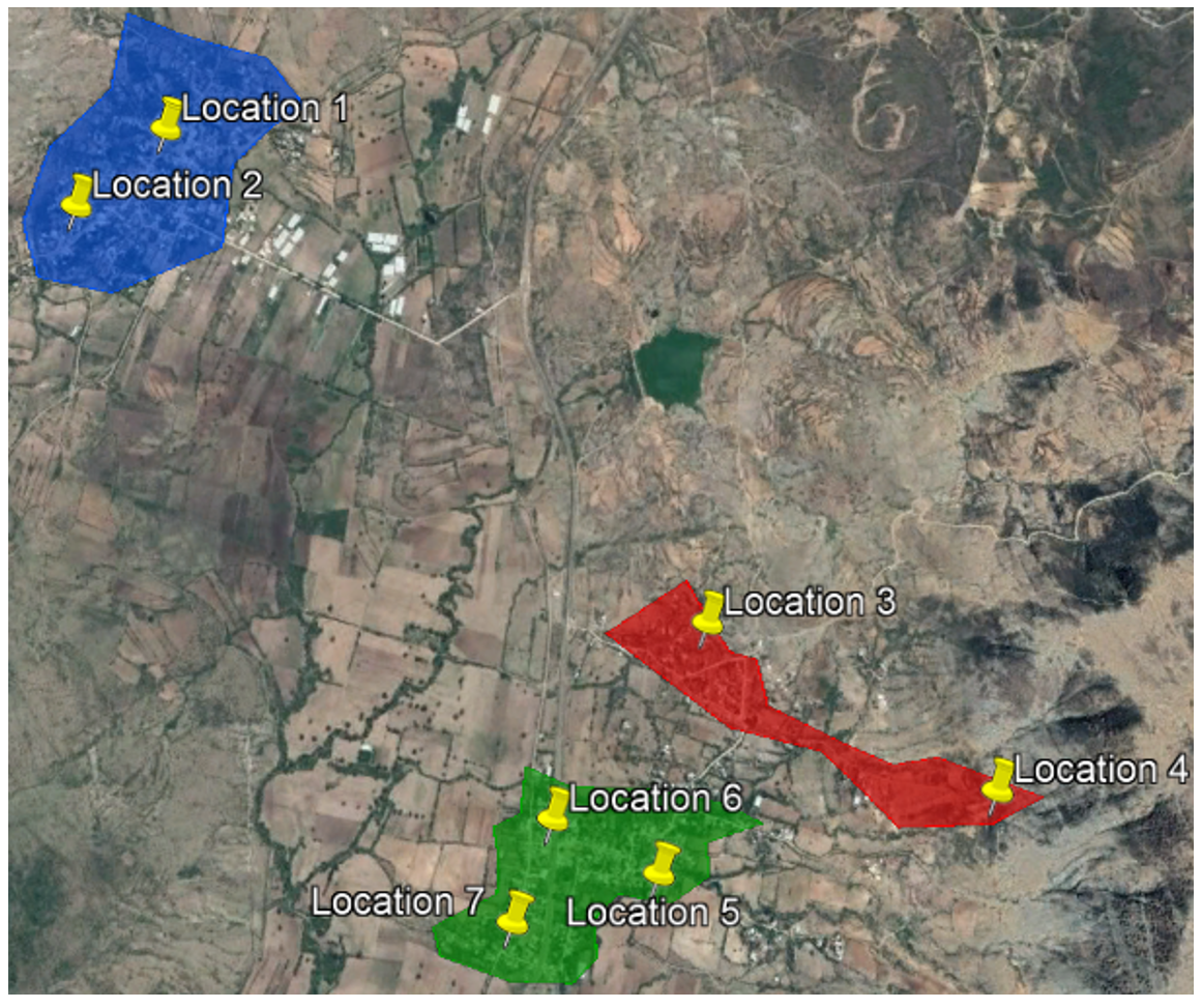
Figure 6. Definition of possible sub-regions for the example region.
- Based on NaaS Operators resources availability, it can be decided that only one Site Survey team can be afforded. In this case, the deployment schedule shall consider 7 days for the required site survey activities. In this case there is no need for the definition of subregions as one site survey team will oversee all locations.
4.2 Site Survey Activities
This section provides a description of the site survey activities and guidelines to carry out each activity involved. In addition, instruction on how to gather photographic evidence will be reviewed. The goal is to obtain relevant information for each use case such as structural information present on site as well as any installed equipment. It must be noticed that site survey activities focus on any NaaS Operator existing equipment. Information regarding existing equipment belonging to other operators will be used only to measure available space on tower as will be descriptive in section 4.2.5.
NaaS Operators are provided with a Site Survey Report Template which can be customized based on each site identified use case(s).
4.2.1 Sites Basic Information
Upon arrival at the location, the survey team must collect all available data to help other teams (site construction team, I&C team, etc.) to quickly identify and access the site. Data to be collected is described below.
- General Information: This information can be obtained directly on the location by reading a nearby street plate, by using an updated map of the region or, as a last option, using Google Earth information. Data to be obtained in this step is:
- Coordinates, references, and site access: This section is composed of the following data:
- Site Access: Description of conditions to obtain access to the location.
- Obstacles Location at floor level: One team member must step at the center of the location with the compass and identify all obstacles surrounding the location. Obstacles located must be clearly identified and displayed in the 360 Obstacles figure. Figure 7 illustrates an example of an obstacle location.

Figure 7. Obstacle Identification example.
4.2.1.1 Photographic Evidence
Table 10 describes required pictures for the Site’s Basic Information section.
|
Item |
Description |
|
Access Road |
Image to display how the access to the location looks like. Example is shown in Figure 8. |
|
Front Facade |
Image of locations front facade showing main entrance. Example is shown in Figure 8. |
|
Sites Panoramic View |
Images displaying all sides of the location (Front, back and sides). |
|
Rooftop view |
Image(s) displaying as much as parts of the base station as possible. Example is shown in Figure 9. |
Table 10. Sites Basic Information photographic evidence.
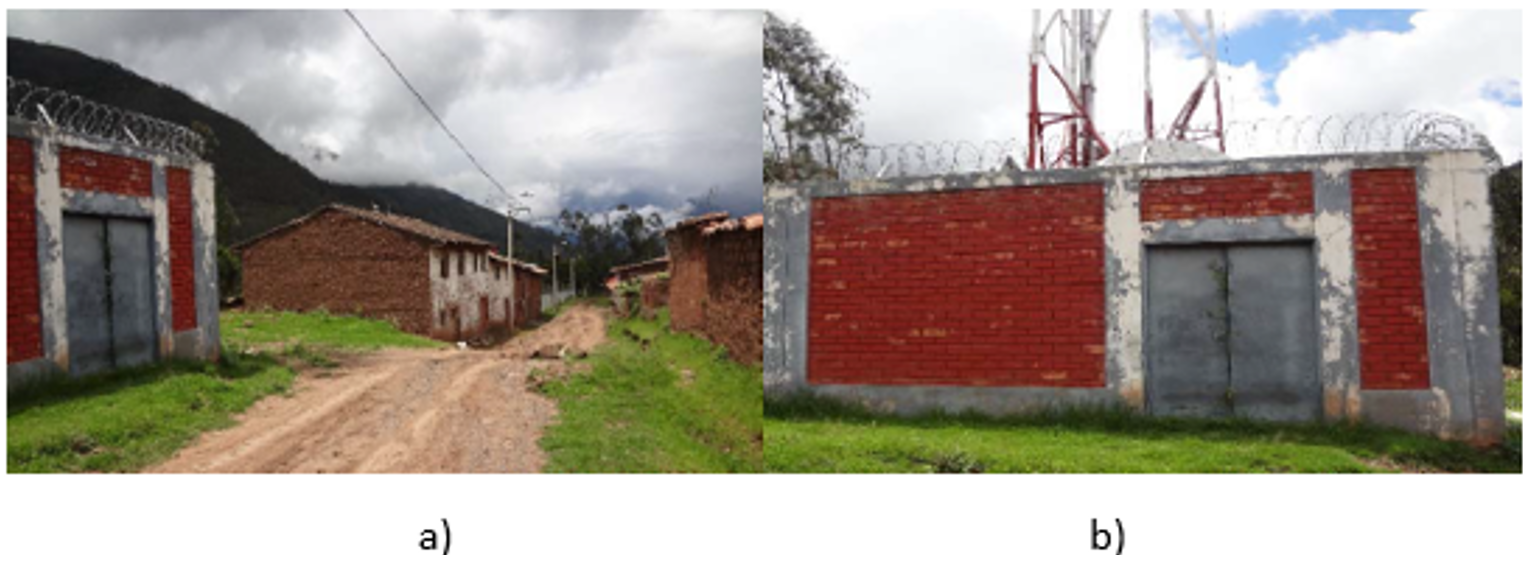
Figure 8. Main Access and Front Facade pictures. a) Main Access Road, b) Front facade.
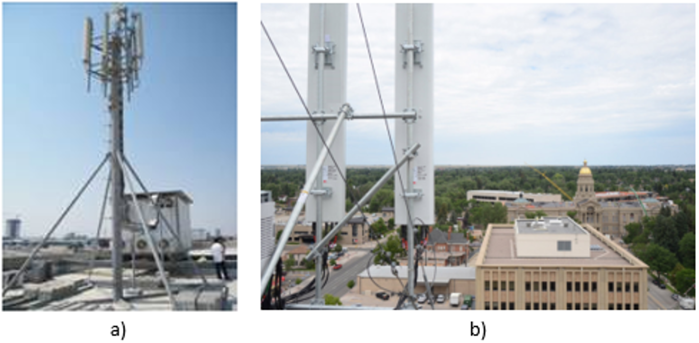
Figure 9. Rooftop view. a) Base Station view, b) Panoramic view.
4.2.2 Civil Infrastructure Survey
Civil Infrastructure refers to data regarding locations structure and, if present, data about any construction made on the location. Data to be collected in this step is:
- Terrain Surface: Survey Team must measure sites main perimeter and record an overview of the location. All objects and buildings inside the location (which cannot be removed and are part of the location itself) must be displayed in the drawing as well as the orientation of the site. Figure 10 displays an example of how the location’s sketch may look like.
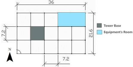
Figure 10. Location overview drawing.
Information to be measured in this step:
- Existing Site Conditions: Team must run a quick evaluation (in terms of integrity: presence of fractures, stability, etc.) the conditions of the structures inside the location. Structures to be evaluated are:
- Existing Tower: Team must collect basic information about tower infrastructure, which includes:
4.2.2.1 Photographic Evidence
Table 11 describes required pictures for the Civil Infrastructure Survey.
|
Item |
Description |
|
Terrain Panoramic |
Image (or images) that display the entire inner structure of the location. Example is shown in Figure 11. |
|
Terrain Ground Plan Sketch |
Drawing of the terrain surface as described for Figure 10. |
|
Foundations |
Clear image of any foundation present in the location. Figure 12 displays examples of tower and cabinet foundations. |
|
Tower panoramic |
Pictures from all angles of the existing tower as shown in Figure 13. Each angle must be documented (i.e. angle A, angle B, etc.) |
Table 11. Civil Infrastructure Survey photographic evidence.
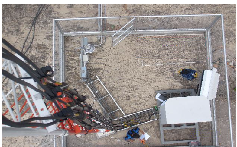
Figure 11. Terrain Panoramic.
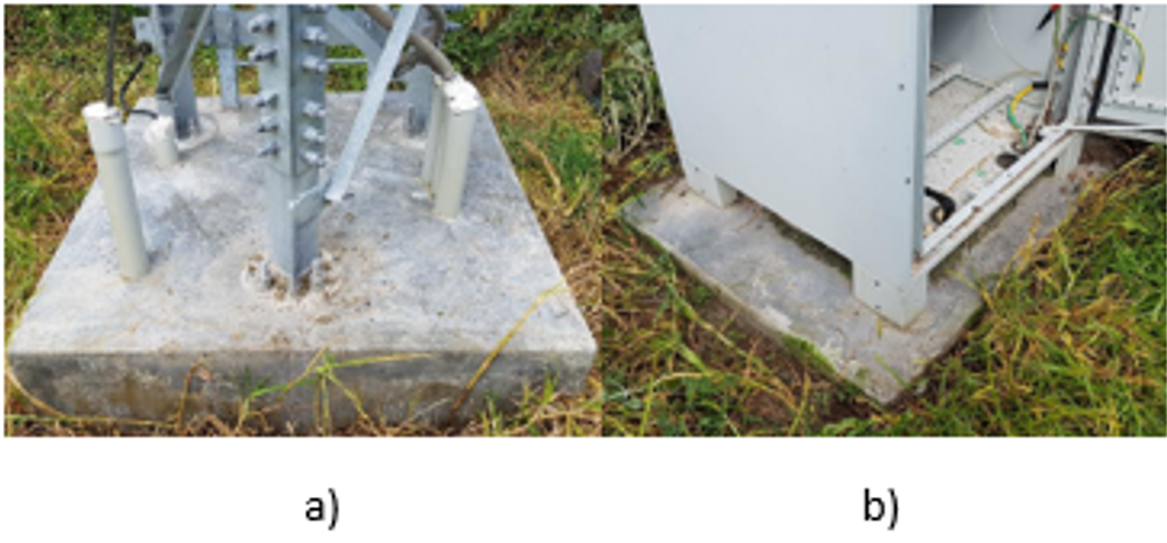
Figure 12. Terrain Foundations. a) Tower foundations, b) Cabinet foundations.

Figure 13. Tower Panoramic.
4.2.3 Power Supply Survey
Power Supply survey must capture data about grid connections, grounding systems and elements to energize any equipment on site. Required data for this survey is:
4.2.3.1 Photographic Evidence
Table 12 describes required pictures for the Power Supply Survey.
|
Item |
Description |
|
Main energy panel |
Front images of the main energy panel. If it has a door, both closed and opened images must be taken. Examples are shown in Figure 14. |
|
Alternative power source |
Images of the alternative power sources: solar panels or eolic generators. |
|
Rectifiers |
Images to clearly identify existing rectifiers and where they are stored. Image of vendor plate with its main characteristics. Example is shown in Figure 15. |
|
Batteries |
Images to clearly identify existing batteries and where they are stored. Image of vendor plate with its main characteristics. Photographic evidence is similar to rectifiers image (Figure 15). |
|
Indoor / Outdoor Ground Systems |
Image displaying the grounding system used by indoor and/or outdoor equipment. Example is shown in Figure 16. |
|
Tower Ground System |
Image(s) displaying all available ground systems for equipment mounted on towers. Example is shown in Figure 17. |
Table 12. Power Supply Survey photographic evidence.

Figure 14. Main Energy Panel. a) Closed, b) Opened.

Figure 15. Rectifiers & Batteries. a) Inside cabinet, b) Information plate.
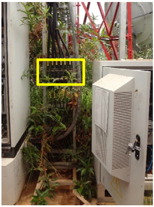
Figure 16. Outdoor Ground System.
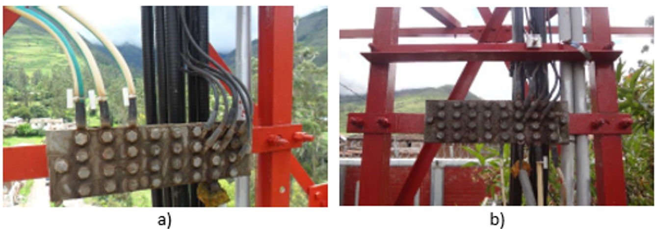
Figure 17. Tower Ground Systems. a) Ground system on top of the tower, b) ground system at the towers base.
4.2.4 Telecom Infrastructure Survey
Telecom Infrastructure Survey must identify, describe, and gather evidence of the available infrastructure where telecom equipment is to be installed. Such infrastructure includes cabinets, racks, wall openings and cable trajectories. Information to be collected is composed by:
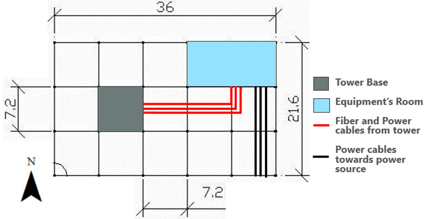
Figure 18. Cable trajectories sketch example.
4.2.4.1 Photographic Evidence
Table 13 describes required pictures for the Power Supply Survey.
|
Item |
Description |
|
Outdoor / Indoor Cabinet(s) and/or Racks |
Images of the indoor and outdoor cabinets and/or racks front panel. Both closed and opened images must be taken. Examples are shown in Figure 19 (outdoor) and Figure 20 (indoor). |
|
Wall Openings and indoor cable racks |
Images to display cable openings (cables going through the wall) and how many cables going on of the cable racks. Example is shown in Figure 21. |
|
Outdoor cable racks |
Images to display outdoor cable racks and how many cables are going through it. Figure 22. |
|
Cable Trajectories. |
Images to display the trajectories of the cables. They should display the main trajectories taken by the cables on their way to/from equipment. Example is shown in Figure 23. |
Table 13. Telecom Infrastructure Survey required photographic evidence.
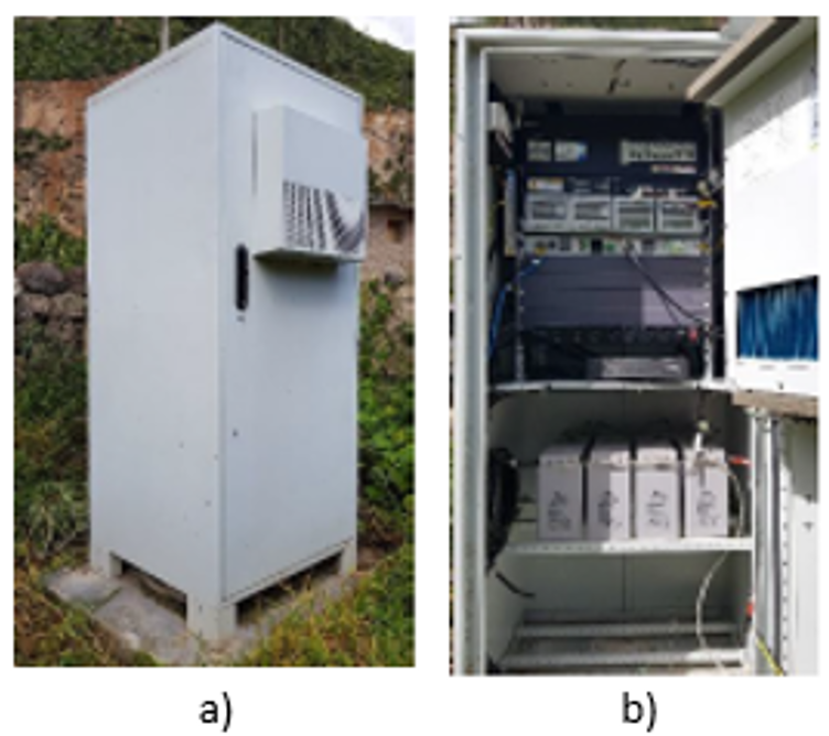
Figure 19. Outdoor Cabinet picture. a) Closed, b) Opened.
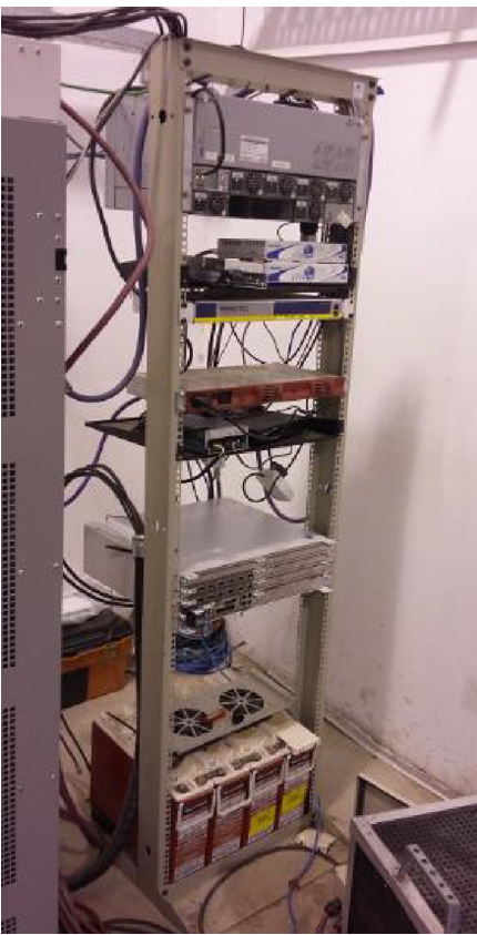
Figure 20. Indoor rack picture.
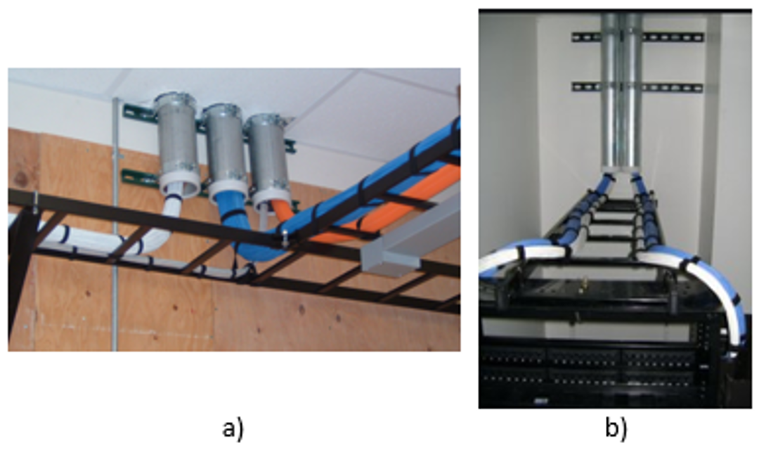
Figure 21. Wall Openings and indoor cable racks. a) Wall Openings, b) Indoor Cable Rack availability.

Figure 22. Outdoor cable racks.
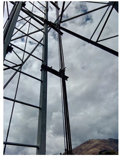
Figure 23. Cable trajectory towards tower.
4.2.5 RF Survey
RF Survey is intended to collect data about the location’s environment to be used for the evaluation of the proposed HLD RF configuration. In addition, information about NaaS Operator existing radio equipment present in the site must be obtained as well. If equipment present on site belongs to other operator(s), site survey must only focus in understanding how it limits the available space on tower and where new equipment can be mounted.
Required information to be obtained from the RF survey is:
- For an existing tower: Evidence must be taken about available space in which new equipment can be installed. Images can be taken at floor level; however, this task must be done by a certified professional if the tower is tall and climbing is necessary.
- Existing RF equipment: If there is an existing base station and NaaS Operator is planning to reuse the installed equipment (i.e., for an overlay deployment), the survey team must get information about the installed equipment and configuration. Required data is:
- Number of antennas on the tower.
- Antenna model May need to climb the tower.
- Azimuth of each antenna Using the compass, see where the antenna is aiming to.
- Tilt of each antenna Using the clinometer next to the antenna to measure its tilt.
- Location of the Radio Units Radio units can be installed next to the antennas, on the tower or inside the floor cabinet. Surveyors must identify where they are installed and measure the distance between them and the antennas.
- Radio unit model May need to climb the tower.
- Available space for new radio equipment (radio units and/or antennas) if new equipment is to be installed, surveyors must measure the assigned space (negotiated by site acquisition) for the installation of new equipment. The measurement and images can be taken at floor level; however, this task must be done by a certified professional if the tower is tall and climbing is necessary.
- Number of antennas and available space in the tower must be identified and drawn in a tower sketch. Figure 24 displays an example of a tower sketch.
- Existing base band unit: Surveyor must identify the base band unit and evidence its model available capacity slots and interfaces for radio connection.
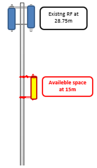
Figure 24. Tower Sketch example.
4.2.5.1 Photographic Evidence
Table 14 describes required pictures for the RF Survey.
|
Item |
Description |
|
Available Space on tower |
Images displaying the available space on the tower for the installation of new equipment. Examples are shown in Figure 25. |
|
Radio(s) units and antenna(s) connections |
Images displaying RF equipment interfaces connections. Close up images are required. A certified professional may be needed if climbing is required. Example is shown in Figure 26. |
|
Existing Radio Units coverage zone |
Images displaying coverage zones of every sector. A certified professional may be needed if climbing is required. Example is shown in Figure 27. Using a compass, the azimuth of the antenna must be measured and noted. |
|
Baseband unit |
Images displaying front and back of the installed baseband unit. Example is shown in Figure 28. |
|
360 Panoramic View at tower level. |
Using the compass, pictures must be taken at tower level covering all angles in steps of 30 (greater steps can be used in homogeneous areas). Examples are shown in Figure 29. |
Table 14. RF Survey required photographic evidence.
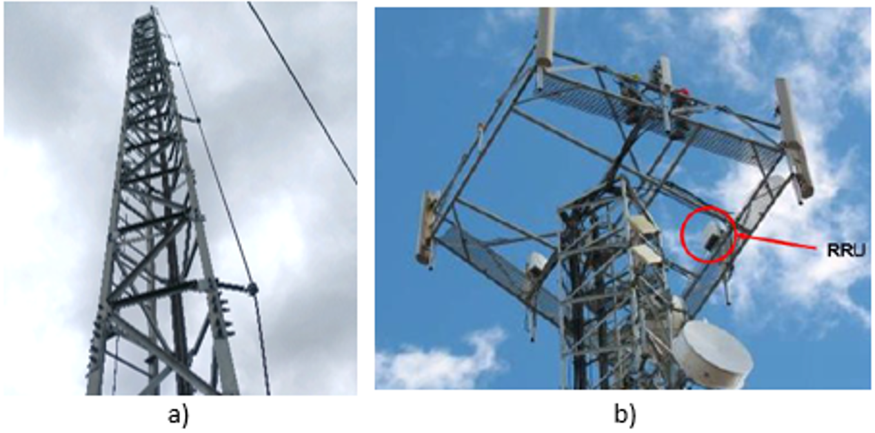
Figure 25. Available tower space. a) Panoramic view, b) Close up to the available space.
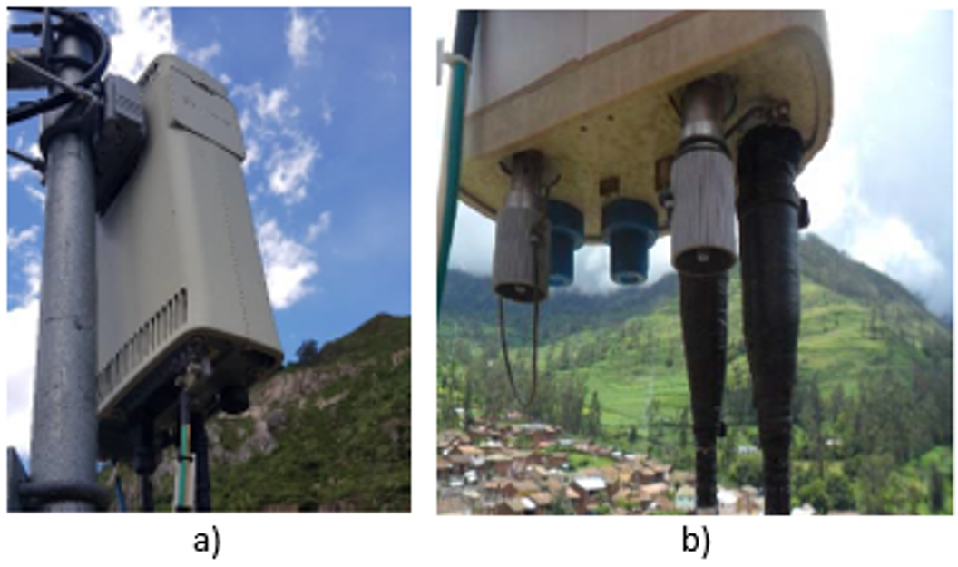
Figure 26. RF equipment interface connections. a) Radio Unit connections, b) Antenna Connections.
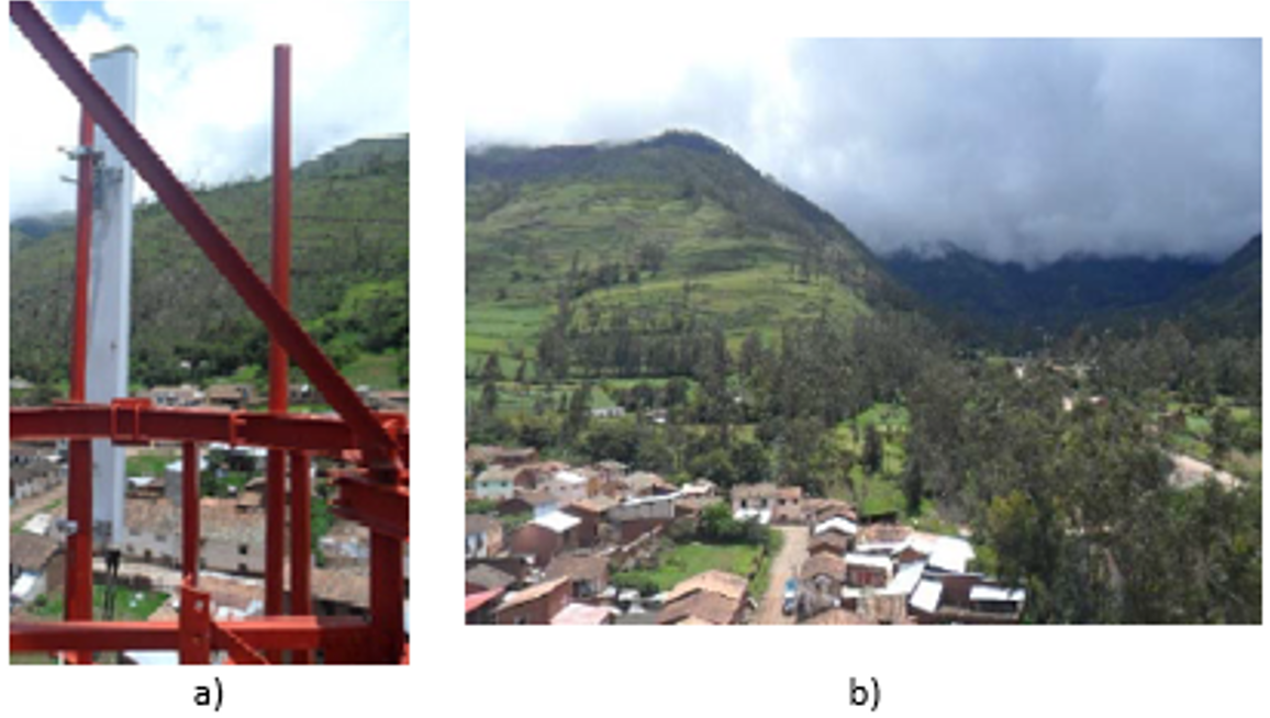
Figure 27. Coverage zone of existing sector. a) Antenna, b) Covered Zone

Figure 28. Installed Baseband unit example. a) Front, b) Back.

Figure 29. Panoramic view at tower level.
4.2.6 TX Survey
TX Survey is intended to get data about the location’s environment to be used for the evaluation of the proposed HLD TX solution. In addition, information about any transport equipment present in the site must be obtained as well. Required information to be obtained from the TX survey is:
4.2.6.1 Photographic Evidence
Table 15 describes required pictures for the Tx Survey.
|
Item |
Description |
|
Fiber connection |
Images displaying fiber connections from fiber source, fiber path and fiber connection to the equipment. |
|
Microwave equipment |
Images displaying microwave equipment installation (on tower, on rooftop, etc.). Close up images may be required. A certified professional may be needed if climbing is required. Example is shown in Figure 30. |
|
Satellite equipment |
Images displaying installed satellite equipment of available space where it can be installed. Example is shown in Figure 31. |
Table 15. TX Survey required photographic evidence.
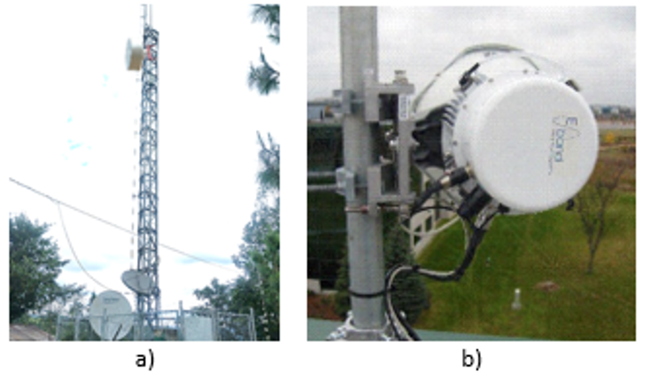
Figure 30. Microwave antenna mounted on tower. a) Panoramic View, b) Close up view.

Figure 31. Satellite equipment. a) Satellite Module, b) Satellite antenna.
4.2.7 Site Survey Activities Customization
Depending on the defined use case, not every site survey activity may be required to be carried out. Table 16 matches each use case with its required survey activities.
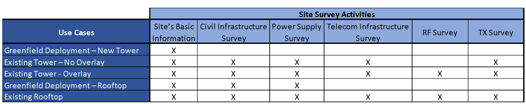
Table 16. Matching between Use cases and required survey activities.
4.3 Documentation
This section will provide guidance for the compilation and formatting of the Site Survey evidence for the generation of the Site Survey report. In addition, guidelines will be given for the customization of the Site Survey template based on the defined use cases
4.3.1 Site Survey Template Customization
The Site Survey Report Template has one sheet dedicated to each site survey activity. Each sheet allows the insertion of data, images, and addition notes (if required). Based on the required use case, sheets which do not apply to the specific use case can be ignored. This way, the resultant report will contain only relevant information for the specific location.
4.3.2 Site Survey Report Customization Generation
NaaS Operator can use the Site Survey Report Template for the generation of its own version of an SSR.
The template allows the required images from each site survey activity to be inserted in its corresponding area. The Site Survey team shall select the best pictures (the clearest ones and those which reflect what was required) in order to avoid ambiguities for those who may use the SSR. In addition, any image can be formatted to highlight a desired feature of the picture. Figure 32 displays an example of an image formatting to highlight, in this case, batteries inside a cabinet.
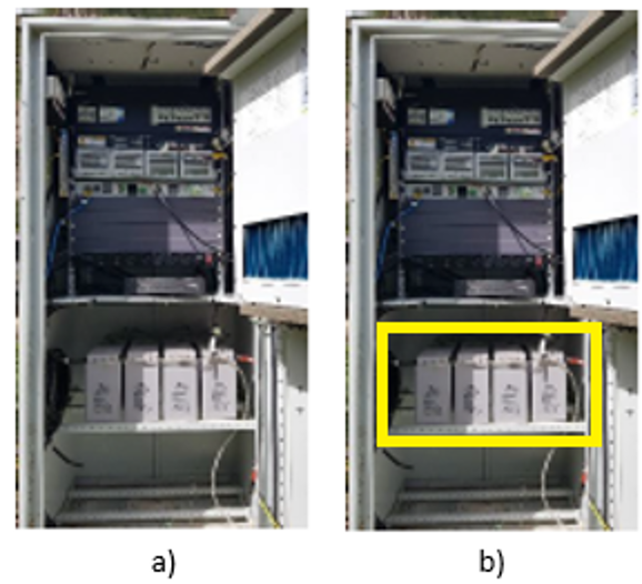
Figure 32. Example of image formatting. a) Original image, b) Formatted image highlighting batteries inside cabinet.
1. Installation & Commissioning Introduction
The Installation & Commissioning (I&C) Module provides the NaaS operator with background information and recommendations to develop their own I&C strategy, including the selection, training, and support of field technicians who perform activities onsite.
This module also provides guidelines for the NaaS operator to prepare their own I&C tasks, create their own installation methods of procedure (MOPs), develop their own how-to commissioning guides, elaborate step by step integration methods of procedure and define their own installation acceptance criteria and test procedures.
This module consists of three sections:
The process described in this module was developed following a low-tech model, which can be defined as the I&C strategy for the organizational structure, procedures, and tasks designed to support and facilitate the field staff jobs in the NaaS rural operator scenario.
1.1 Module Objectives
This module will guide NaaS operators in planning their strategies and processes for the disparate installation scenarios, and help improve speed and quality of the implementation following the first time right approach (fundamental for NaaS implementation in rural scenarios). The module focuses on the following objectives:
1.2 Module Framework
The framework shown in Figure 1 displays all NaaS playbook modules and their relationship to this I&C module. The Strategic Plan & Scope and High-Level Network Architecture modules provide the business and technical context for the NaaS operator and directly impact many aspects of deployment.
The I&C module is included within the deployment stream. It takes inputs from the RAN & Transmission LLDs and the generated output, serving as the required input for Operations & Maintenance module.
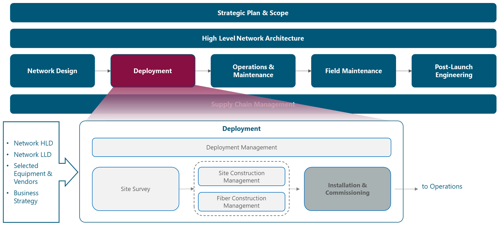
Figure 1. The network deployment and management framework.
Figure 2 presents the I&C process view, where the inputs and tasks are exhibited.
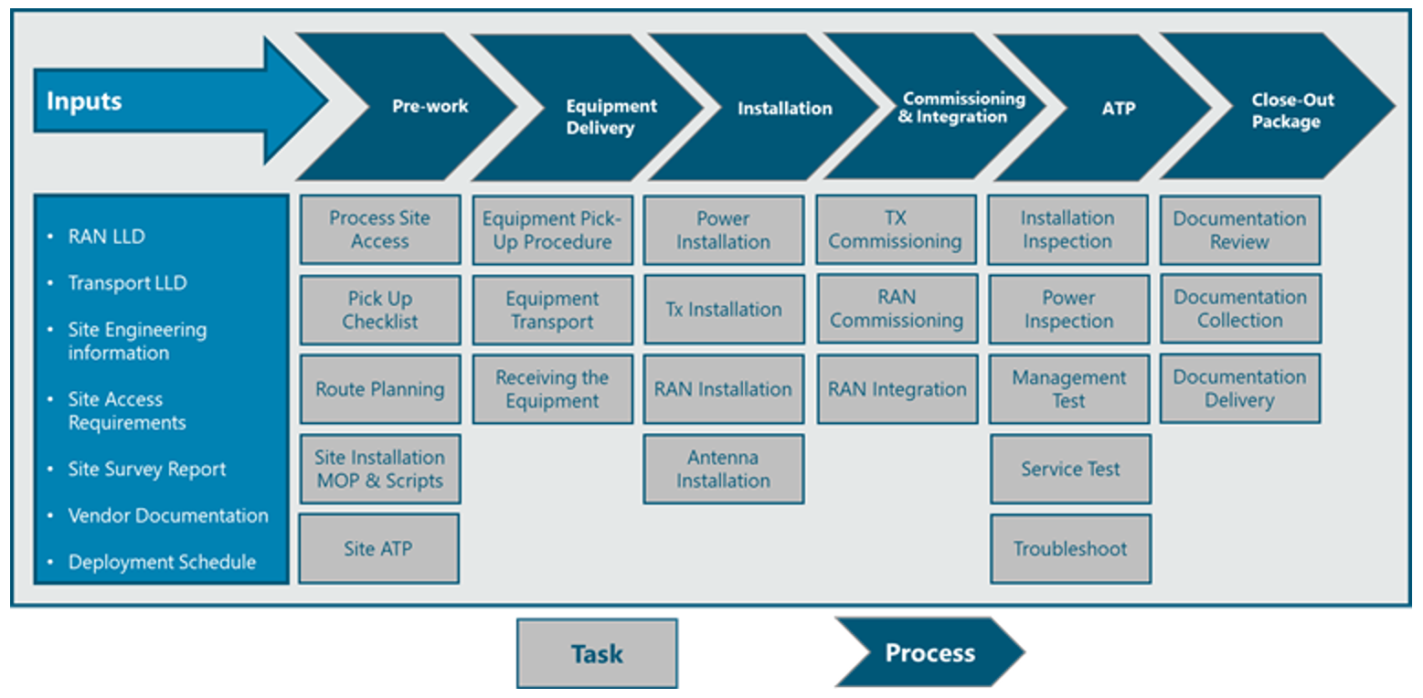
Figure 2 Installation & commissioning process view
2 Installation & Commissioning Process Overview
This section presents a high-level overview of the main tasks, inputs, pre-requisites, and requirements for the whole Installation & Commissioning Process. The process includes I&C Task preparation (Pre-work), Equipment Delivery, Installation, Commissioning, Integration, Acceptance Tests and Close-Out Package.
2.1 Installation & Commissioning Prework
I&C prework is any preparation that comes before hands-on work. It involves a series of tasks required to facilitate field works, thereby decreasing the probability of issues, ensuring the first time right approach, and optimizing the entire process. Some of these tasks are: obtaining access permits, identifying site representatives and points of contact (PoC), and preparing transportation routes to the site. It includes adapting previously developed MOPs, checklists, scripts, and acceptance test procedures (ATPs), thereby streamlining the process that must be customized for each site.
Figure 3 illustrates the prework process. Left-side blocks represent inputs from the TX LLD, RAN LLD, and other sources. I&C prework having customized MOP, checklist, guideline, and pre-requirements outcomes are shown at right.
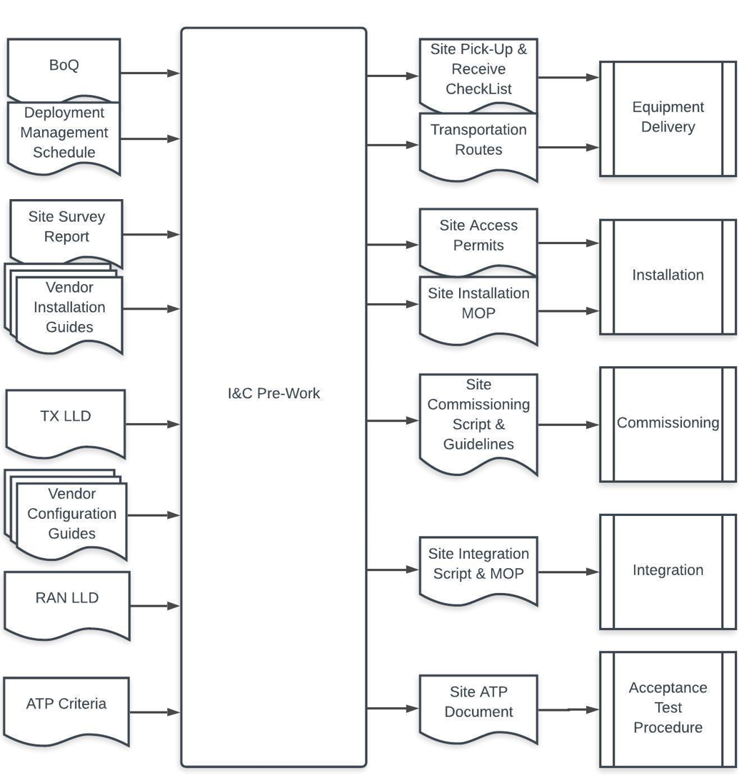
Figure 3 I&C functional view
Prework tasks are described in section 4.2.1, which includes step-by-step guidelines and recommendations for the NaaS operator to prepare their own I&C tasks.
2.2 Equipment Delivery
In the NaaS operator scenario, equipment delivery to a site is especially difficult for various reasons, such as sites being located far from warehouse distribution centers or cities, or roads being in bad condition (making equipment delivery an expensive and arduous task). Thus, transportation of network equipment, ancillaries, and tools must optimally be done in one shipment.
Delivery starts at a local warehouse, where the network equipment and ancillaries are collected by field personnel who will perform the installation. NaaS operators can choose to hire shipping services; this decision may depend on many factors, such as route challenges, tight schedules, or assigned budget to this task.
The local warehouse personnel must be prepared with the predefined kits for each site (see section 3.4 for more detail), these being properly documented in a pickup checklist that includes information about who will pick up the equipment.
Section 4.2.1.3 contains useful considerations to help optimize the transportation process of the network equipment, tools, and ancillaries from a warehouse to the site. It also includes instructions to elaborate a pickup checklist template, used as a pre-requirement to pick up network equipment, tools, and ancillaries from a local warehouse. A generic pick-up and reception checklist templates can be adapted by NaaS operators for receiving everything onsite.
2.3 Installation
Installation takes place after the Field Supervisor has validated that all field personnel are properly equipped with safety gear and tools onsite, thereby helping ensure their safety.
Figure 4 shows a Base Station common scenario which uses Microwave as the Backhaul Technology and the Network equipment is installed within a shelter at the base of a tower. RAN equipment antennas and radio units are mounted for this case at the top of the tower.
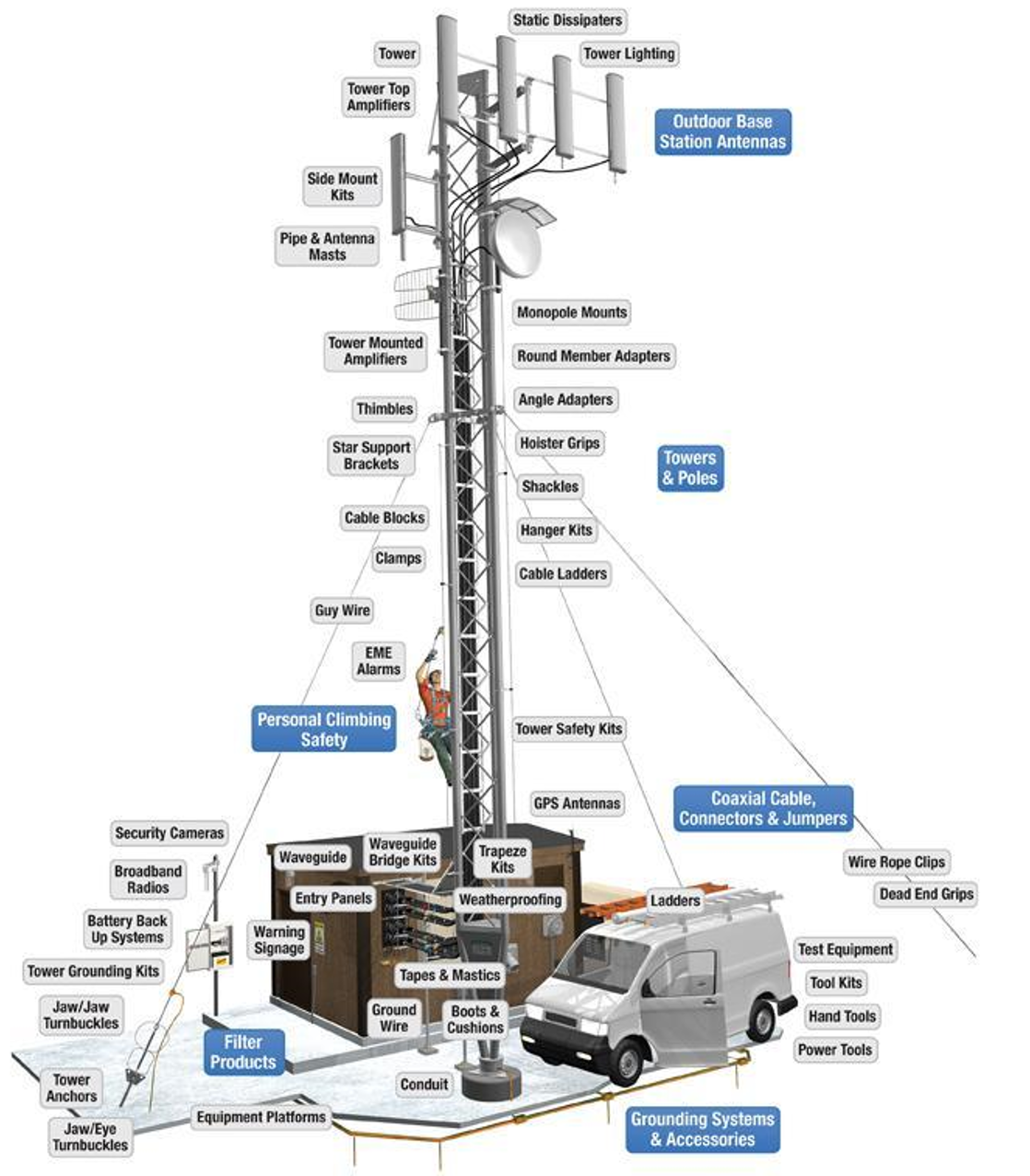
Figure 4 A common base station scenario
2.3.1 Backhaul Equipment Installation
Backhaul equipment installation will depend on NaaS operators Tx design. NaaS operators network may include disparate technical solutions as detailed in the following subsections.
2.3.1.1 Microwave Backhaul
For microwave, there are two mounting solutions split mount and full outdoor:
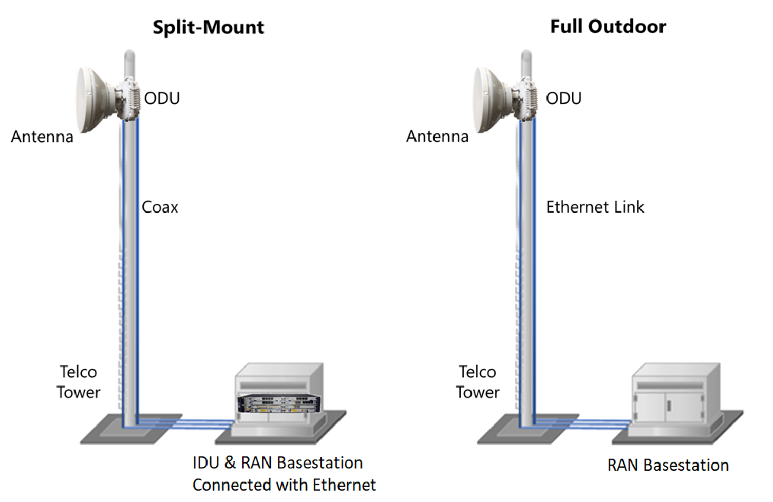
Figure 5 Microwave installation scenarios
2.3.1.2 Satellite Backhaul
The satellite backhaul solution consists of a very small aperture terminal (VSAT) with a remote router or VSAT modem connected to a small (typically 1.2m to 3.8m diameter) dish via a coaxial cable. The VSAT modem is connected through an Ethernet interface to the base station.
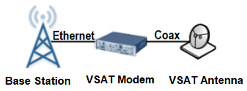
Figure 6 Satellite backhaul solution
2.3.1.3 Fiber Optic Backhaul
With fiber optic backhaul, a site router or switch must be installed and a last-mile fiber optic cable from the site to the transport providers network must be deployed (see the Fiber Construction Module for more detail). The NaaS operator must request the transport providers (i.e., FiberCo) connectivity services, ensuring transport availability by the time the site is to be integrated. The transport service is to have been tested and reported to ensure performance and availability of the transport link (this is critical and should be performed before RAN equipment installation begins).
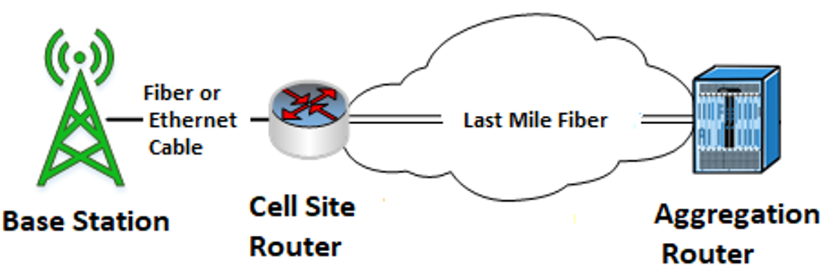
Figure 7 Fiber Last-mile construction
2.3.2 RAN Equipment Installation
For RAN equipment, installation scenarios will depend on selected vendors, site type (macro or small cells), indoor or outdoor installation. Tasks include the installation and cabling of the baseband unit (BBU), radio units, and antennas. Figure 8 shows the most common scenario in rural deployments: the baseband, rectifiers, and batteries are installed within IP55 outdoor cabinets at the base of a tower or monopole; antennas and radios are at the top of it. Fiber optic cables are connected between the BBU and radios alongside the tower and are secured with fiber clips. In a similar way, power cables run from radios to power equipment. Antennas and radios are interconnected using RF cables.

Figure 8 RAN equipment installed in a monopole
This configuration may vary depending on the scenario documented in the MOP defined for each site (described in section 4.2.3), which the field supervisor must follow; this ensures installation methods are in line with the NaaS operators predefined procedures. Installation is complete when all site elements in the receive checklist are in place and verified by the field supervisor.
Section 4.2.3 will guide the NaaS operator how to create their own installation MOP for RAN, transmission, and power equipment for the low-tech NaaS operators field crew. Generic installation MOP templates are provided to be adapted by the NaaS operator with the NaaS administrative, security, and standard procedures, and in accordance with vendor equipment or the installation scenario.
2.4 Commissioning & Integration
Commissioning tasks involve turning on the transmission and RAN equipment, configuring it, debugging, and validating that the end-to-end service works properly. Transport setup includes configuring the required connections to reach a working IP network. RAN configurations include connecting to the core network elements to which the site is related, such as the O&M system, MME, S-GW, and neighbor eNBs.
The commissioning script is commonly prepared by an integration engineer and previously shared in the prework phase with the field supervisor. The commissioning script file is loaded to the transport equipment and includes preconfigured routes to reach the core from the RAN site.
When the transport is successfully configured, the RAN base station is also commissioned. Optimizing the overall procedure, this process configures the base station without having to manually do so.
Under ideal conditions, the field supervisor should receive constant support from the integration team that monitors whether the site can be reached from the core side; both teams work together if troubleshooting is required. Integration tasks may start once the site is reached from the O&M system.
The integration team ensures the site is fully operational and ready for commercial use as part of the NaaS operators network. During this integration phase, the team loads RAN LLD parametrization, configures base station alarms, and site visibility in the O&M System. Additionally, it collaborates with the field supervisor to troubleshoot and clear any external or configuration alarms.
This procedure is discussed further in section 4.2.4 and includes two process diagrams.
In the NaaS operator scenario, the core network composed by MME, S-GW, and IMS might belong to a mobile network operator (MNO). If this is so, the NaaS operator integration team should previously coordinate with the MNO team to configure interconnections between the core network elements and base station.
Once the base station is configured and integrated, the next step is to validate connections between network elements, synchronize the network, and inspect base station performance data in the network management system. Interworking of network elements, as well as the functionality of alarms and recovery systems on a network level are tested.
Section 4.2.4 contains considerations for the NaaS operator to develop its own how-to commissioning guidelines for the low-tech NaaS operators field personnel. It provides a generic commissioning and integrations guideline template to be customized by NaaS operators, dependent upon vendor equipment and including an evaluation of tools and activities prerequisites.
2.5 Acceptance Test Procedure
An acceptance test procedure (ATP) is a critical process before bringing the site into commercial service. Its a multi-step process that involves field tests to validate the hardware installation quality and test the end-to-end service. It verifies site performance in the field as a customer would experience it.
The procedure follows previously defined criteria established in the ATP document, customized for each site and validating each of its elements:
|
● RAN base station |
● Radios |
|
● Transmission equipment |
● Power equipment |
|
● Antennas |
● Cabling and grounding |
The ATP includes a photo report that proves installation has followed the NaaS operators MOP and quality standards.
An acceptance test report is a critical document to transfer site responsibility to the operations team. Naas operators can use this report for other purposes, such as a trigger for invoicing and payment to vendors or third-party services managed by supply chain management.
See section 4.2.5 for more information, which contains considerations for the NaaS operator to define its own installation acceptance criteria of the base station, power, and antennas to develop a step-by-step ATP for the low-tech field personnel. It includes guidelines for the NaaS operator to define their operability and service tests to be included in the ATP, and provides a generic ATP template to be customized by NaaS operators depending on their own acceptance criteria.
2.6 Closeout Package
The closeout package consists of the collection, organization, review, and delivery of all relevant information generated before and during I&C (e.g., site acquisition, construction, I&C and acceptance test reports). As a best practice, its important to define the responsible party for elaborating each document through the deployment phases.
Once each party has theirs ready, they upload it in a site tracking tool or document repository such as Dropbox or Google Drive organizing the documentation on a site-by-site basis. This activity will prove that vendors and service providers followed all the contract agreements and their objectives have been met. The closeout package facilitates future operation and maintenance tasks.
Section 4.2.6 provides a generic closeout package checklist to be customized by NaaS operators, dependent upon their generated documentation within the I&C process. Additionally, Section 4.2.6 evaluates documentation management platforms to be considered within NaaS operator tools.
3 Installation & Commissioning Strategy
In RAN sites located in rural locations, the I&C process plays a critical role in achieving a successful and affordable rollout. NaaS organizations must tailor their processes to their scenario, as well as develop a strategy to overcome challenges in rural deployments. These have their own characteristics, where site access is generally difficult (location far from warehouse distribution centers, cities, or even paved roads). I&C must therefore be conducted with a goal to perform it first-time right, avoiding repeated site visits that can result in delays and cost overruns. The following subsections analyze strategies that NaaS operators might follow to fulfill the required tasks.
3.1 Insource vs Vendor Outsource
A NaaS operator can choose to have its own collaborators be responsible for carrying out I&C tasks (insourcing), or contract a third-party company to undertake it (outsourcing). Insourcing implies that NaaS operators have the required job profiles within their organization or that they can hire additional workforce. On the other hand, choosing to outsource I&C activities requires an extra investment. Therefore, sourcing selection implies a tradeoff between spending financial resources on a third party, building an internal team with the resources that NaaS Operators already have or hiring additional collaborators.
3.1.1 Insourcing Scheme
With respect to insourcing, having an internal employee handle matters lets NaaS operators customize their process if its required, since such staff can respond to changes more quickly than if theyre subject to outsourcing. Additionally, insourced employees can move to other tasks after the I&C process, such as network maintenance, where they’ll need less management and likely make fewer mistakes than an outsourced person who feels no loyalty to the NaaS operators business.
Note that with insourcing, the cost of required tools, vehicles, and personal protective equipment is absorbed by NaaS organization, so its best practice to take care of these tools so they may be used in forthcoming phases.
3.1.2 Outsourcing
With outsourcing I&C tasks, its most common to hire professional services from vendors or consultants. Vendors organize their own team, including implementation managers, project managers, specialized RAN and core integration engineers, among others. Offered services will vary depending on the agreement and very likely will increase the cost but facilitate the entire deployment.
If NaaS operators choose to outsource personnel, then payroll, additional benefits and (US) Social Security taxes are the outside contractors responsibility. Depending on the agreement, additional costs such as tools, vehicles, and personal protective equipment can be included in the contractor agreement.
Additionally, outsourced contractors provide a great deal of flexibility to the NaaS organization; their service can be used at the convenience of the NaaS operator. This is especially helpful in situations where the implementation is altered in some way. For example, if a regional rollout is halted due to any reason that doesnt depend on the NaaS operators plans, then there is no need to stop the work and maintain idle resources.
Below is a list of NaaS operators outsourcing responsibilities:
Overseeing the progress of key I&C tasks will help in keeping a record of when milestones are completed for each site per the planned schedule . Contractor reports may be used as a trigger for milestone completion. Reviewing all activity reports will improve quality by locating works that need improvement (or reworks if necessary), until the required task meets the expected outcome.
3.1.3 I&C Roles
For the following roles, NaaS operators must evaluate if each can be covered by insourced staff or require outsourcing.
Field Supervisor
A field supervisor permits flexibility in overseeing the installation; they can oversee installation at more than one site if tight scheduling exists. In addition, they might manage multiple installation crews if this is required. The following tasks are considered within the field supervisor scope:
Due to these role requirements, its recommended to insource this resource whenever possible, since their required expertise will be useful in forthcoming phases (up to maintenance of the network).
Installation Technicians
A team of installation technicians can perform the installation and cabling of network equipment and, depending on the established scope, might also perform commissioning.
If network expansion is not soon planned and NaaS operators have field supervisors within their organization, then its recommended to outsource the installation technicians, if possible.
Integration Engineer
Integration engineer is a specialized role requiring deep technical knowledge of the network equipment and technology, so the NaaS operator may consider engaging an integration consultant service to perform the following tasks:
Due to the characteristics of the tasks that integration engineers perform which most of them are performed just during the deployment, NaaS Operators may consider outsourcing the integration engineer role.
3.2 The Low-Tech Model
Another option is to develop a strategy that reflects the NaaS operators own conditions. This strongly depends on choosing personnel who know the deployment area and are able to work in challenging field condition seven if they don’t have full technical knowledge to perform more complex I&C tasks. Under these conditions, this playbook introduces the low-tech model; its an approach for NaaS operators to adapt their organization, processes, and tasks to achieve the first-time right goal using low-tech personnel.
The low-tech model is a strategy for the NaaS operator to obtain field technicians locally for I&C tasks. This is only provided if there is enough support from all other stakeholders through all process phases, the objective being to facilitate their tasks in difficult rural environments. This is to ensure the quality of site work and meet each target date on time.
This model considers four key stakeholders: the deployment manager, the integration engineer, the field technician, and the warehouse manager. Together they can perform certain actions, in addition to their present scope, that will support the field technician at the various I&C stages.
The Deployment Manager
Integration Engineer
Field Supervisor
Deployment Team
Figure 9 shows a visual representation of the low-tech model:
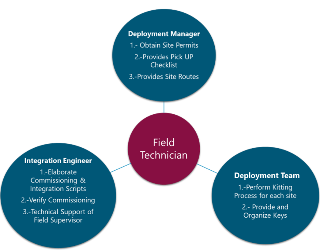
Figure 9 The low-tech model
NaaS operators must decide on one of the presented approaches and tailor it for their organization. Table 1 provides advantages and disadvantages of the low-tech model.
|
Advantages |
Disadvantages |
|
Lower cost of operation (cost savings is expected to be critical in rural deployments) |
Training may be required |
|
Overall increased control of the deployment |
Additional tasks are added to other team members |
|
No need of third-party vendors in their operation |
Finding experienced resources locally may be challenging |
|
NaaS operators will learn to deploy an installation rollout (useful for future expansions) |
Deployment may be slower due to employee learning |
Table 1 Advantages and disadvantages of the low-tech model
low-tech model should be considered under the following circumstances:
3.3 Technician Training
As part of the low-tech model and in compliance with local authorities, NaaS operators should consider a training program for field technicians and supervisors to ensure they have the knowledge to safely work with power equipment and work on towers at height. Additionally, its recommended to perform training regarding how to properly install and commission sites, as this will result in better deployment quality, speed, and efficiency.
A NaaS operator can develop training with the following considerations:
Specific features of the training plan may include:
If the low-tech field technician gets proper training and there is support for them in the field, the cost-benefit ratio in the short- and long-term will be higher, (e.g., the NaaS operator will be able to deploy sites faster and the same resources could be used in the future for maintenance tasks).
3.4 Kitting Process
Kitting is a material management strategy used to create prepackaged and prelabeled components, thereby increasing efficiency and reducing time-consuming organization of equipment delivery. Kits simplify the supply chain by combining several network equipment pieces and ancillaries that are always used together into a single kit (dependent upon installation scenarios).
A NaaS operator can use these steps to create a kitting program that eliminates SKUs and streamlines the supply chain:
The following table shows an example of kitting an outdoor site:
|
Rural Site : RUR2020 |
||||
|
Kit # |
Description |
Component |
Quantity |
Code |
|
1 |
.Outdoor grid power |
Power distributor X |
1 |
SKUSR |
|
Rectifier vendor X |
1 |
SKU1KMFBR |
||
|
Battery cabinet vendor X |
1 |
SKUSCV1 |
||
|
Breakers vendor X |
10 |
SKUBRK01 |
||
|
Battery vendor X |
6 |
SKUBTRY01 |
||
|
2 |
SAT backhaul |
Vsat-DISH |
1 |
SDKUVSDSH |
|
Vsat modem vendor 2 |
1 |
SKUMV2 |
||
|
Coaxial cable 30 mts. |
1 |
SKURRUV2 |
||
|
Ethernet cable |
1 |
SKUDRANT |
||
|
Connectors |
2 |
SKUSFP |
||
|
Mounting ancillaries |
1 |
SKUFIBR |
||
|
3 |
Outdoor baseband x2 sector 2x2MIMO |
Radio unit vendor 2 |
2 |
SKURRUV2 |
|
Directional antenna vendor 5 |
2 |
SKUDRANT |
||
|
MM SFPs vendor 2 |
4 |
SKUSFP |
||
|
MM fibers vendor 2 |
2 |
SKUFIBR |
||
|
Baseband unit vendor 2 |
1 |
SKUBBU |
||
|
Cabinet for NW equipment |
1 |
SKUCAB |
||
4 Process Definition
Processes provide a way to communicate and apply consistent standards and practices within NaaS operations. A procedure defines activities to be undertaken, who performs them, their purpose, how they are performed, and who is responsible. Once worked through, a process provides an efficient way of performing a given task in a consistent way, thereby greatly reducing reworks since all know exactly what, when, and how to perform their tasks.
This section provides a generic process NaaS operators might use as a reference in defining their own processes that better suit their organization. It also includes guidelines to help NaaS operators develop their own administrative and security processes. Additionally, it contains instructions to create their own I&C instrumentation, such as a checklist, MOPs, and guideline templates.
4.1 Administrative & Security Process Definition
In Greenfield scenarios, the site is acquired before the installation by the NaaS operator; thus, the responsibility of taking care of the security, safety, and legal procedures belongs to it. The NaaS operator must assign a site owner to be responsible for the security of the site, predefining their administrative and security procedures for site visits on a site access procedure. For existing sites where a installation space is leased (e.g., MNO towers or a private building), site owners must inform the NaaS operator about their access request requirements, the operator then considering those requirements as part of their own procedures.
This section evaluates site access procedures, including safety and legal requirements. NaaS operators may consider these procedures as prerequisites to work on their site facilities, thereby avoiding security issues and ensuring field worker safety while avoiding legal penalties.
4.1.1 Safety Procedures Definition
Prior to allowing anyone to work on a site, a relevant risk assessment and a safe work procedure (SWP) must be developed and provided to the site owner.
Safety procedures are detailed documents that cover the implementation of safe work systems. As such, they constitute a mandatory element in attaining the required safety standards given either by industrial standards or by law. Its imperative that the NaaS operator be informed of local regulations and ensure that all field workers follow the safety procedures.
Below there is a set of considerations for NaaS Operator in order to develop their own Safe Work Procedure.
The above considerations are just an example of NaaS operator safety procedures; please review local regulation requirements.
The deployment manager or field supervisor is to ensure that the safety procedures are kept up-to-date and under constant review in light of feedback from operational experience and safety audit reports. Changes are to be initiated where existing safety procedures are found inadequate or in need of improvement. As a best practice, NaaS operators may include a checklist in their installation MOPs. The Check-list will ensure that field workers perform the required safe work procedures, requiring each field worker sign that theyre in compliance. Then the document must be included in the close-out package.
4.1.2 Security Procedures Definition
A NaaS operator and site owners may use a security control with an access procedure to control visitors to the site. Visitors must obtain written authorization from the site owner before entering the site. This should be submitted to the site owner with the access request form. Field workers must carry relevant records of their competency and a copy of the safe work procedures on each visit to the site.
Field technicians who access a site for any reason might perform potentially hazardous tasks or have the potential to interrupt a service of another company; here the site owner must know which activities are being undertaken on their site. The more information visitors can provide, the better. As a best practice, site access can only be given for the permitted use described in an approved access request form. Any additional work or variations to the initial proposal must be submitted to the site owner or infrastructure owner for further approval. An access request form template is provided for NaaS operators to adapt to their own security standards.
4.1.3 Security Requirements
A NaaS operator may consider adding working periods in their access request form to avoid work overlap during that period. This is to avoid unauthorized visitors and enhance the control of any security issue. Overestimation of access times can be refused, especially where such access inconveniences other service users. Underestimations of access times must also be avoided, as they often lead to service interruptions due to work running overtime.
Additionally, to control access during the commissioning and integration process, all stakeholders must previously request access to the network to the NaaS operators network operation center (NOC), providing their user ID so as to perform the network configurations (this has been previously mentioned in the NaaS operator scenario, as the core network could belong to a mobile network operator (MNO). If this is the case, the NaaS operators integration team and MNO personnel can schedule integration of the RAN site with the MNO core network (this is commonly performed by MNO staff).
4.2 Process Guidelines and Instrumentation
The following sections provide guidelines for the NaaS operator to prepare for the I&C tasks, create their own I&C MOP, define acceptance test criteria, and properly manage all the generated documentation using the most appropriate tools and methods.
4.2.1 Pre-Work Guidelines
Before installation procedures, a set of tasks must be prepared to enable seamless work, thereby avoiding delays and rework that result in cost overruns. The scope of the prework task is to ensure all requirements (e.g., BOQs, site survey reports, TX LLD, RAN LLD, vendor installation and configuration guides) are in place in preparation for the following tasks:
In this way, all requirements will be ready before field technicians arrive at the remote sites. A best practice is to identify points of contact (PoC) for each requirement; each will upload their respective documents to cloud platforms such as Google Drive, DropBox, or SharePoint. In this way the information can be easily referenced.
In addition, the NaaS operator must identify the PoC or site owners for each site so as to coordinate access and activities. All these prerequisites can be used as a go/no go enabler to initiate equipment transportation tasks.
This module provides a prework checklist template to ensure all inputs and prerequisites are complete before hands-on, in field operations.
4.2.1.1 Access Permits
Access permits are required regardless if the site is owned by the NaaS operator or is leased on an MNO tower or private building. The owner of each site must be properly identified before performing the site access procedures. A best practice is to perform the procedure several days in advance (the number of days will depend on each site owner); this must be done for each work visit to every site.
The deployment manager might carry out this activity, sending the access request form to the previously identified site owner with the required identification of all NaaS operator field technicians. The NaaS operator might use the access request form template for this purpose.
4.2.1.2 Equipment Pickup Checklist
After a NaaS operator has defined the kitting process, the warehouse manager, deployment manager, and field technician must be aware of each equipment piece to be installed. This is to follow the RAN LLD BOQ detailed in a pickup checklist prepared for each site that details:
The checklist must be shared and signed by all stakeholders. As a best practice, it must be included in the closeout package as proof that the equipment left the warehouse. A NaaS operator may use the equipment pickup checklist template for this purpose.
4.2.1.3 Route Planning
Depending on the deployment plan and for multiple reasons (e.g., optimize NaaS operator vehicle use) equipment delivery might include visiting more than one site . Improving the planning process to reduce the number of trucks, miles, and drivers can increase business efficiency.
Here is a set of considerations for rural route optimization:
A good practice is to develop a spreadsheet that includes the site address; this can be imported to a planning route tool. Several free online tools can help plot a route, the easy-to-use Google Maps likely being the most popular. And its possible to export the route spreadsheet to Google Maps, enabling the tracing of a destination site route and determining which sites are close to the it.
See https://www.google.com/earth/outreach/learn/visualize-your-data-on-a-custom-map for more information.
4.2.1.4 Installation MOP Generation
Once a Naas operator has created its own MOP, it should be adapted for each installation site, reflecting the specific site information, power equipment, transmission technology, and RAN scenario.
This is an essential part of the low-tech model, addressing field technicians with the specific task to perform (thereby avoiding possible mistakes and achieving successful ATPs).
4.2.1.5 Commissioning Script Generation
Before the installation task can commence, the TX LLD must reflect each network element IP address, including the IP link between the base station and O&M system.
The integration engineer needs this information to generate the commissioning script that is to be loaded in the local base station.
4.2.2 Equipment Delivery Guidelines
Equipment delivery involves warehouse personnel, field technician(s) and the deployment manager.
4.2.2.1 Preparation
Field personnel must have their badge or personal identification, have double-checked that they have brought all required tools and safety gear, that all is in optimal condition. They must also have verified their vehicle is in good condition and its documentation is readily available. Additionally, they have gathered their transportation routes, site permits, keys or codes, and a copy of the equipment pickup checklist provided by their deployment manager.
Previously shared by the deployment manager, warehouse personnel must be aware who is to pick up the equipment.
4.2.2.2 Equipment Pick-Up
A best practice is for both local warehouse and field personnel to double-check the network equipment and ancillaries. Afterward the validation, field technician and warehouse personnel must sign the equipment pickup checklist which must be used as proof that the right equipment was delivered to the field technicians. Both, warehouse personnel and field technicians must keep a copy of the document. Field personnel must follow the transportation routes and report to the deployment manager when they arrive at each site included in the route.
4.2.2.3 Receiving the Equipment
Once the field personnel and equipment arrives at the site location and administrative and security procedures are performed as defined in section 4.1, the receiving task is carried out. This entails unpacking previously assembled kits, filling the site equipment reception checklist, and verifying that all equipment arrived in optimal condition. This task must also be performed if a shipping company delivered the equipment. When the receiving task is complete and field personnel properly rested , the installation task can be performed.
4.2.3 Installation Guidelines
This section guides the NaaS operator about how to create its own MOP for RAN, transmission and power equipment installation for the NaaS operators low-techfield crew.
For NaaS operators to develop their own installation MOP, this section provides a set of considerations, analysis, and useful examples used in actual installation rollouts. As a best practice, NaaS operators might consider organizing their procedures in three distinct MOP documents that will guide the field technicians tasks:
A best practice is to layout MOP tasks in chronological order (as seen in the example below):
|
Power Equipment Installation MOP Contents |
Backhaul Equipment Installation MOP Contents |
RAN Equipment Installation MOP Contents |
|
1. Access Request 2. Health & Safety Measures 3. Preinstallation Procedures 4. Connection Diagram 5. Equipment Description 5.1 Power Equipment Installation 5.2 Cabling & Labeling |
1. Access Request 2 .Health & Safety Measures 3. Pre-Installation Procedures 4. Connection Diagram 5. Equipment Description 5.1 Antenna Mounting (Microwave or VSAT dish) 5.2 IDU or Modem Mounting 5.3 Cabling & Labeling |
1. Access Request 2. Health & Safety Measures 3. Preinstallation Procedures 4. Connection Diagram 5. Equipment Description 5.1 Antenna Mounting 5.2 Radio Unit Mounting 5.3 Base Station Mounting 5.4 Cabling & Labeling |
Table 3 Chronological MOP installation tasks by type
The table shows the MOP content for power, backhaul, and RAN equipment installation. Note that the Access Request and Health & Safety Measures entries are the same procedures for all documents, so a NaaS operator might consider splitting those sections into another document.
This module provides generic installation MOP templates for power, backhaul and RAN to be adapted by NaaS operators. The following section is an analysis of a generic MOP for RAN equipment installation.
4.2.3.1 Access Request
The MOP should include a section that indicates the task that a field technician must perform step-by-step to request site access, as previously defined by the NaaS operator and described in section 4.1.3.
4.2.3.2 Health & Safety Measures
The installation MOP must contain a set of tasks to prevent injuries and detail the PPE that field technicians must wear during equipment installation tasks. NaaS operators must include and consider those tasks as a prerequisite for equipment installation procedures, as was previously defined in section 4.1.1.
4.2.3.3 Pre-Installation
Preinstallation tasks are a set of validations field technicians must perform before equipment installation. A NaaS operator can consider it as a prerequisite before the hands-on installation tasks and add it to their MOP. A list of tasks the NaaS operator can include in their MOP follows:
1. Site Material Received
A field supervisor or technician must verify all equipment is delivered to the site according to the receive checklist and is in good condition. A best practice is to include a copy of a receive checklist in the MOP.
2. Details of Tools and Testers
A MOP might include a list of tools and testers at the beginning of the document; to save them time, this will help ensure the installation technicians have all the required tools before climbing a tower or entering a private site. Figure 10 shows common tools used in RAN equipment installation.

Figure 10 Common tools used in RAN equipment installation
3. Verify Weather Conditions
The field supervisor must verify weather conditions before work is done in heights. Best practices should not allow work in heights where winds velocity exceeds 30Km/h. Water, snow, or ice accumulated on the tower should be an indication that installation tasks should stop until conditions improve.
4. Winch Installation
Installing heavy components in heights will require a winch or a crane that uses iron cables; the winch must be fixed on a completely stable structure.

Figure 11 Commonly used winch for tower installation
Installation procedures can start when the winch is properly installed.
4.2.3.4 Connection Diagram
To achieve a better understanding, for each installation scenario a connection diagram, showing the interconnection between network elements, must be developed for RAN, backhaul, and power equipment.
Figure 12 shows RAN connection diagram samples. Depending on scenario complexity, a single diagram could cover all connections or it could be split upfor example, power connections in one diagram, with fiber and RF connections in another.
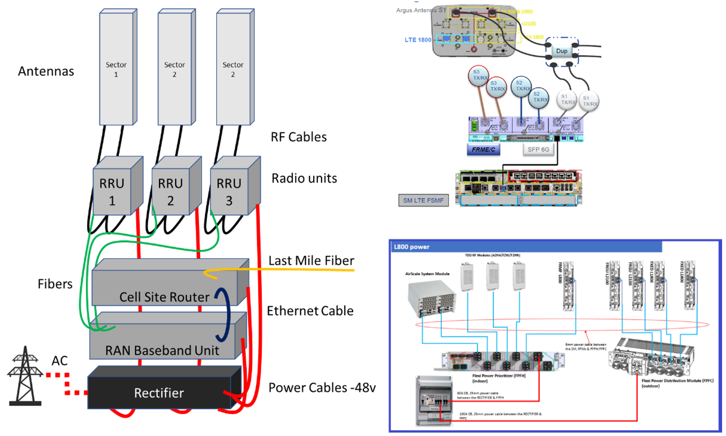
Figure 12 Connection diagrams used in an actual MOP
The MOP must clearly depict the installation scenario. In the Figure 12 example, it considers the following: three-sector scenario MIMO 2X2 with fiber backhaul and a rectifier that takes power from the grid. Connection diagrams are intended to represent a high-level overview of the entire installation and don’t require the use of actual equipment images. Additional details for connections procedures could be detailed in equipment installation sections.
4.2.3.5 Equipment Description
To further define installation tasks, a short description of each network equipment element must be added to the MOP: illustrative images of actual network equipment can be included that identify all physical interfaces. This information can be obtained from vendor documentation.
Figure 13 shows an illustration of the physical interface of a RAN base station, radio unit, and antenna ports.
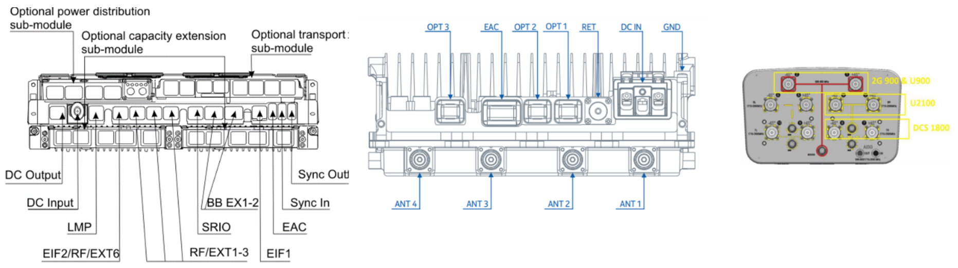
Figure 13 General physical interfaces of RAN equipment
4.2.3.6 Ancillaries List
The MOP can include a list of ancillaries required to install the equipment especially those used for equipment to be installed at height (e.g., antennas and radio units). This can help ensure that field technicians have everything in their bag before climbing a tower, thereby saving time in their tasks. Required ancillaries for each equipment element must be listed in vendor documentation. Figure 14 shows ancillaries required for a radio unit installation:
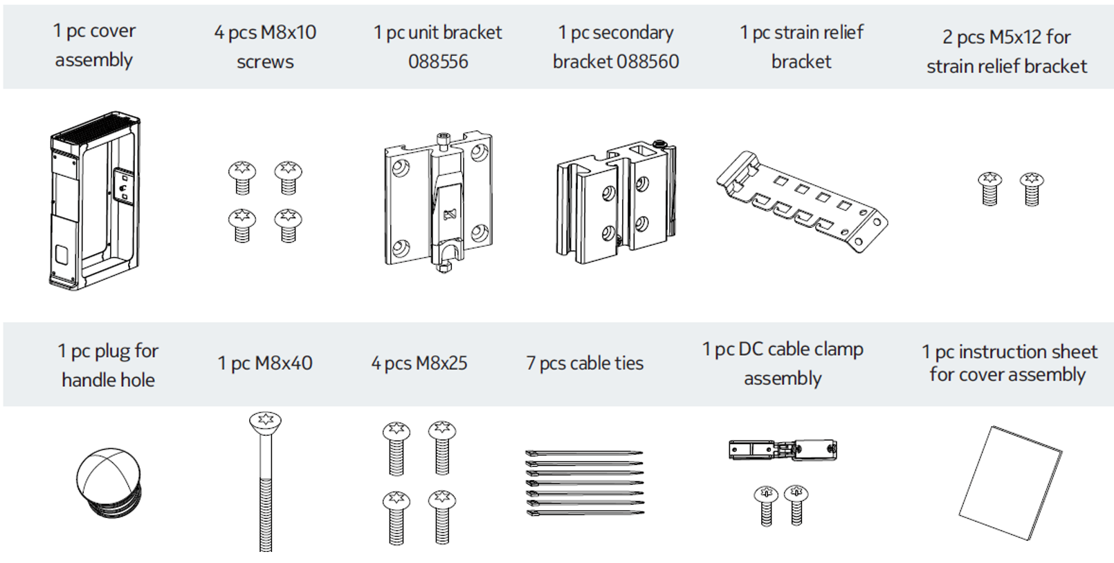
Figure 14 Ancillaries required for the installation of a radio unit
4.2.3.7 Equipment Installation
The equipment installation procedure will depend on facility characteristics, backhaul technology, and vendors the NaaS operator has chosen.
Using the installation guidelines of each vendor, this procedure should be detailed step-by-step and as clearly as possible in the MOP. The MOP can include engineering diagrams from vendor documentation or actual photos from previous installations. The next set of illustrations are a sample specifically for RAN equipment installation, radio unit mounting to a pole, and grounding of the radio unit.
Radio Unit Mounting.
1. Lifting the Radio Unit :
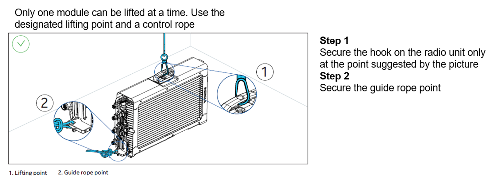
2. Installing the Radio Unit on a Pole:


3. Cabling the Radio Unit on ground:
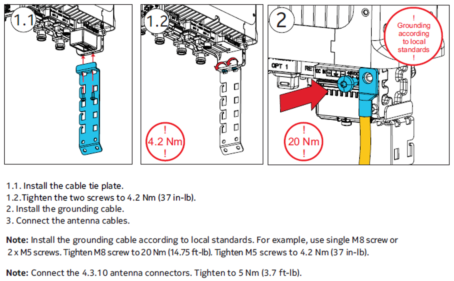
Specialized Installation Procedures such as Microwave Antenna RF Antennas can be reviewed in the Primer Antenna Installation Procedures which provide a set of instructions to lift and install the Antennas in Tower. This module also provides considerations to follow during Power Installation Equipment in the Power Installation MOP template.
This module provides a generic installation method of procedure templates for power, backhaul, and RAN equipment that a NaaS operator can adapt for their own scenarios.
4.2.3.8 Labeling
Labeling is an important task of any installation procedure; it enables an easy management of cabling by identifying each one that is connected to each network equipment component. Labeling is especially important during the maintenance phase, when a team who didnt construct the site needs to troubleshoot equipment.
NaaS operators must define the cabling standards for all connections, including labeling for the following cables:
As a best practice, labels must be affixed at both ends of each cable and a code should be established for each cable type. Figure 15 shows an example for jumper cables in thean antenna:

Figure 15 Labeling of RF jumpers
In Figure 15 the RF jumper cables are labeled with three red marks and one yellow mark. The meaning will depend on a NaaS operators own standards. Labeling should be added in the MOP, where a best practice is to include a table with the labeling requirements/standard.
4.2.4 Commissioning and Integration Guidelines
Transmission commissioning refers to the process that creates the links between the core network and the management system; its considered as a prerequisite of RAN commissioning and depends on the core functions. This commissioning process depends on the transmission scenario, since the process differs between commissioning a site cell router, microwave system, and a satellite modem.
Vendors of each scenario must provide detailed documentation to commission their equipment. NaaS operators must read and understand this documentation, in addition to addressing it with their field personnel.
RAN vendors use different methods and instructions for commissioning their equipment. For example, there are vendors with features that permit automatic discovery of the base station in their O&M system under certain conditions and without manual intervention. NaaS operators can evaluate if this feature is applicable in their network and is within their budget.
This section analyzes some processes that NaaS operators can consider to facilitate C&I tasks; they depend on the operators staff profiles.
Different options are detailed, considering the balance of tasks between field technicians and integration engineer:
4.2.4.1 Preconfigure equipment in the local warehouse
This option lets an engineer load a commissioning script, license file, and software upgrade package to the baseband unit at the warehouse. Its then powered off and taken to the planned site where, after power-up, the remaining portion of the integration is performed remotely from an O&M system. Preconfiguring equipment under controlled circumstances saves time at a site, where backhaul is less robust and can cause reception delays of the configuration files. Additionally, if troubleshooting is required, its easier for experienced technical staff to be available at a centralized warehouse rather than rural sites.
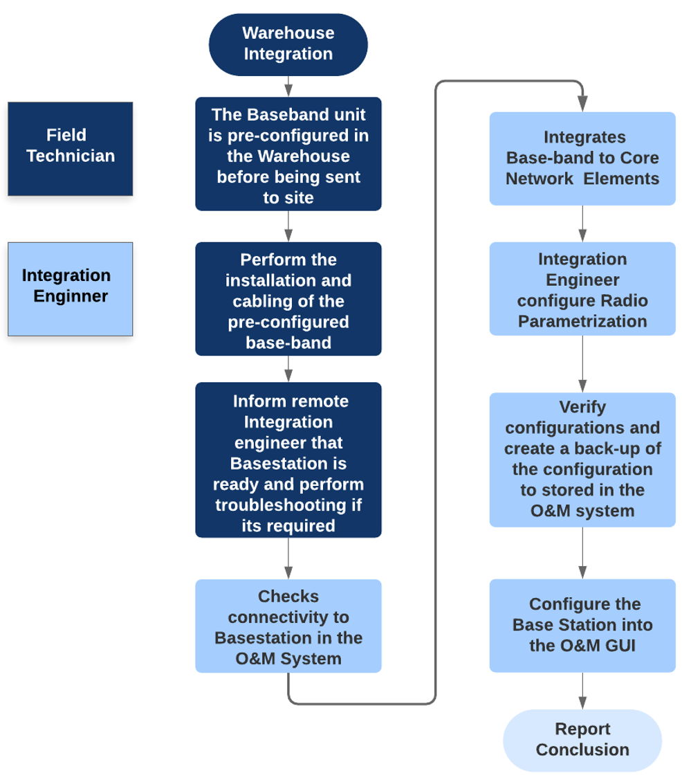
Figure 16 Warehouse commissioning and integration
If its not possible to preconfigure the equipment, a commissioning script should be provided before the field technicians go onsite. Once installation concludes, field technicians power-up the equipment and load the commissioning script (the process is the same as described in Figure 16).
4.2.4.2 Full offsite integration
With this option, the integration engineer configures and integrates the baseband node with the commissioning scripts at the warehouse. They also configure QoS, features, and radio network parametrization there using O&M and CLI software tools. This option requires a stable internet connection at the warehouse.

Figure 17 Full offsite integration process
NaaS operators can customize the process depending on their organization. For example, an experienced field technician could perform the full offsite integration process.
The processes described above are generic that all vendors support. Some vendors permit an auto-configuration of the base station under certain conditions (e.g., self-organized network (SON)) that greatly reduces manual intervention. After NaaS operators develop their processes, they can elaborate their own guidelines.
The scope of forthcoming subsections is to guide NaaS operators in preparing their own I&C guidelines depending on their own scenario. As an example, this module considers the commissioning process, which is performed manually in the warehouse (or onsite) by a field engineer and is remotely supported by an integration engineer. This is a process that all vendors have in common.
4.2.4.3 Commissioning guideline elaboration
NaaS operators commissioning guidelines must be designed with a simple structure containing only that which is required to perform the procedure. Below is an example of a commissioning guidelines structure:
1 Abstract
2 Prerequisites
2.1 Tools
2.2 Configuration Data
2.3 Preparation
3 Commissioning and Integration Process
3.1 Connecting PC to Base Station, IDU or Modem
3.2 Loading Base Station configuration
3.9 Check the IP Connectivity
4 Call Test
5 Concluding Routines
6 Additional Information
Commissioning Guideline Example
Following the warehouse integration, NaaS operators can limit the scope of commissioning up to when the O&M link is createdleaving configurations such as transport network, RF parameterization, QoS, and RF neighbor relations to the integration process.
Below is a commissioning guideline example:
Abstract
This document describes how to commission and integrate the base station into a NaaS network. In all cases, procedures must be followed, regardless whether they are specified in this document.
2 Prerequisites
Before starting integration, the following items must be completed and understood.
2.1 Tools
Thin client or laptop with:
2.2 Configuration Data
IP and router configuration design documents prepared by the design team.
2.3 Preparation
1. Read and understand base station installation documents.
2. Read and understand general requirements when entering live customer sites
3 Commissioning and Integration Process
Perform the following steps to commission and integrate the base station.
3.1 Connecting PC to LTE Digital Unit
1. Power on LTE base station
2. Connect LAN cable (RJ45) to base station port LMT and laptop in LAN port:

(Best practice is to use real image or diagrams of the network equipment)
3. Set IP client as follows (use the real base station IP):
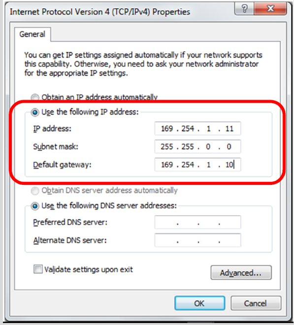
(Best practice: use actual image of the tasks)
4. Connect to base station using the local maintenance tool
5. Fill in RBS IP address (use the O&M IP) then click Connect
3.2 Loading Site Install, Site Basic, and Site Equipment
1. Click Tools > Integrate Base Station (best practice: use actual image of the tasks):
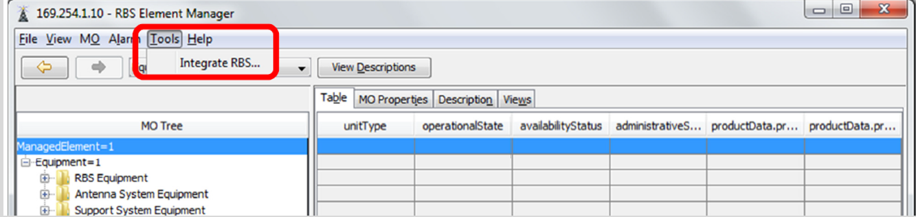
2. Click Browse > Select Site Install script (best practice: use actual image of the tasks):
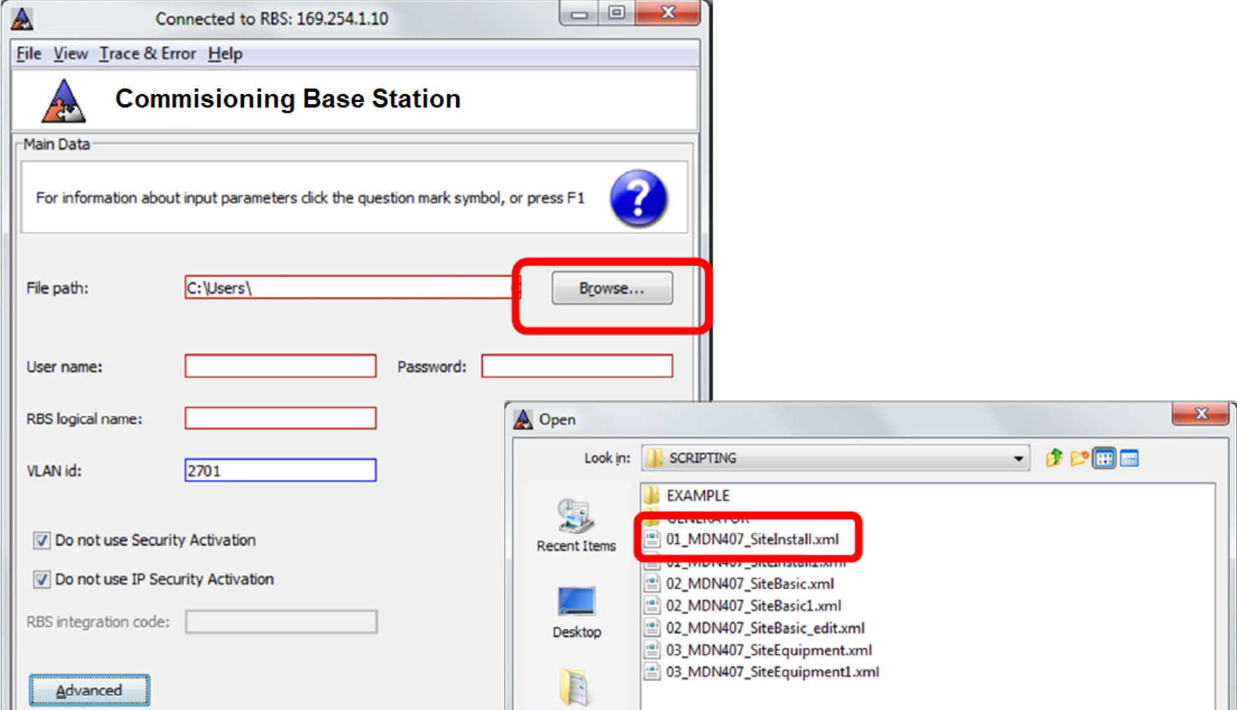
3. Fill in username: <USER> and password: <PASS> then click Next (factory user and password)
The display shows the Site Install script content. It configures:
Once the commissioning has been successfully performed and the link between the base station and O&M system has been created and configured, the integration team can access the base station management system remotely and perform all missing configurations. The following subsections provide guidance over the manual integration model that all vendors support.
4.2.4.4 Integration prework
The integration engineer must prepare the integration scripts and network access permissions before the maintenance window. A maintenance window is a time frame in which NaaS operators can integrate their RAN elements into the MNO core network elements. Commonly this is performed at night to prevent a possible outage and cause minimal impact to end-users.
If the integration tasks have not been completed and the maintenance window exceeded, there may be penalties and a rollback procedure to be carried out. This cancels all progress of the integration tasks and is done to maintain MNO core network data integrity.
Next is a list of some preparation tasks:
4.2.4.5 Commissioning process support
Ideally, the field supervisor or field technician calls the integration engineers to notify them that the equipment has been installed, configured locally, and the transport network and O&M link are online. The integration engineers then try to remotely connect to the site to validate end-to-end connectivity and load the commissioning script. Some issues may arise and a troubleshooting session might be performed in collaboration with the integration engineers to ensure the base station is reachable and can be controlled remotely.
Figure 18 shows the architecture of O&M interconnections to the base station:
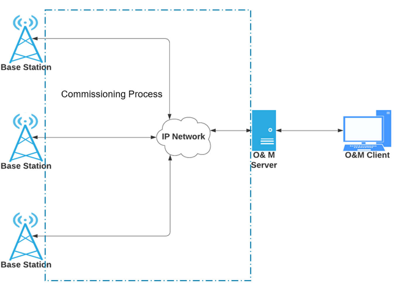
Figure 18 O&M architecture and interactions between commissioning and integration procedures
4.2.4.6 Review base station status
The integration engineer should check the status of the base station elements, reviewing the alarm status. Commonly it will show several alarms, such as 1) there is no license for the base station, 2) there is no contact to the core network elements, or 3) there is hardware that hasnt been configured (e.g., radio units or RET)among other alarms. The integration engineer must clear the alarms, configuring the base station as indicated in forthcoming steps.
4.2.4.7 Configure the base station hardware elements
The base station elements, such as radio units and antenna, must be configured in the base station. Base station architecture will depend on vendor selection; commonly it also includes RF cards to connect the radio units, as well as transport cards to connect transmission equipment by fiber optic or Ethernet cables.
A license must be loaded to configure the base station. The license may contain the number of radio units, maximum allowed power, or features a NaaS operator is permitted to use in the base station. The license is normally controlled and managed using a serial number. After the license has been successfully installed, the next step is to configure the related base station parameters as previously defined in RAN LLD (e.g., transmission power and mechanical tilts).
4.2.4.8 Integrate the missing IP paths to core network elements
The IP connection to the O&M system was created during the commissioning process. Now the integration engineer must configure the missing IP connections to the core elements. As section 2.4 mentions, in the NaaS scenario the core network elements may not belong to the NaaS operator network. Depending on the agreement, the NaaS operators integration engineer can configure the base station in the MNOs core elements during a previously arranged maintenance window, or MNO personnel can carry out the configuration.
Regardless of the agreement, the integration engineer must validate the connection verifying if the user plane and control plane links are working properly. If not, troubleshooting may be required using common techniques such as ping and traceroute to the faulty core element link.
Figure 19 shows an example of RAN element IP configurations.
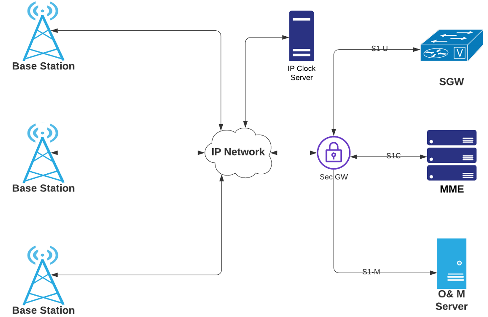
Figure 19 IP configuration of the RAN elements
4.2.4.9 Configure radio parameterization
Radio parameterization from RAN LLD must be loaded into the base station. In this step, the RF parameterization, QoS parameters, RAN features activation, cells parameters, and RF neighbor relations are configured. Using their CLI or GUI, the integration engineer must create or enter this configuration into the parameterization script, accordingly with the vendor equipment instruction set.

Figure 20 Enabled functionalities during RF parameterization
4.2.4.10 Create data backup
Once the user plane and control plane links are operative and cells can be managed, a data backup must be created and stored, with one copy remaining within the base station file system and another in the O&M server. These actions will ensure continuous operability should the base station fail for unexpected reasons, thereby avoiding visits to the remote site.
Most commonly, the integration procedure is made by highly specialized engineers who have deep knowledge of the hardware and software architecture of the network equipment. As was detailed in section 3.2, the NaaS operator can obtain integration services from a specialized consultant depending on the vendor that has been chosen.
4.2.5 Acceptance Test Procedure Guidelines
The acceptance test begins when the integration activities have been completed; its carried out on a per-site basis. This function consists of the validation and acceptance of deployed sites. Each site undergoes a series of inspections, assessing operability, and conducting service tests such as physical site inspections, site management, functionality of alarms, and end-to-end service tests to ensure proper functionality. This process is supported by field and remote personnel. This section guides a NaaS operator in defining their own installation acceptance criteria of the transport, base station, power, and antennas to develop a step-by-step ATP for low-tech field personnel. Additionally, an ATP template is included in this module; it contains prerequisites for each test and detailed procedures to perform the management test.
4.2.5.1 Site information
The acceptance test must be elaborated and filled out for each site for proper identification. Table 4 shows the required data to properly identify the site.
|
Site Name |
|
Site ID |
|
|
|
Coordinates |
|
|
|
|
City |
|
|
|
|
NE ID |
|
|
|
O&M IP |
|
Gateway IP |
|
Table 4 Site information for the ATP
4.2.5.2 Acceptance guidelines
The acceptance test starts after integration concludes; its conducted by field technicians and remote personnel (which could be the integration engineer and/or the NOC).
ATP is performed onsite by the field supervisor or field technician and is supported by the integration team (who performs the operation and maintenance tests). Results are reported and failures should be resolved in real-time.
Site acceptance is achieved when:
4.2.5.3 Installation inspection
An installation Inspection must be performed for physical elements of the site, such as cabinet installation, cabling and labeling, base station, antennas including a visual operative inspection. The following subsections include examples of the objectives, prerequisites, and criteria that can be used by a NaaS operator for reference.
4.2.5.4 Power measurement
A best ATP practice is to measure DC and AC voltage, thereby ensuring that power equipment is working properly and AC is within operative range at the moment of the test.
4.2.5.5 Management test
The management test is a set of tasks that validates that network equipment can be controlled and monitored from remote locations. A NaaS operator can consider the following tests to validate O&M remote control:
4.2.5.6 Service test
A service test proves network performance as a customer would experience it. Therefore, user equipment already registered in the NaaS operator network is a prerequisite for this activity. It must be previously validated to establish it can be performed by the deployment manager or NOC to avoid disturbance in operative sites.
Recommended test services are:
|
● Web browsing |
● Speed test |
|
● CSFB call (if NaaS operator network has WCDMA) |
● Video streaming |
|
● VoLTE |
● Audio streaming |
|
● SMS message |
The provided ATP template in this module contains prerequisites for each test as well as detailed procedures to perform the service test.
4.2.5.7 Troubleshooting
During the ATP remote personnel monitoring the base station should verify its overall performance. Any anomaly should inform field personnel to immediately troubleshoot if its possible; otherwise the issue should be properly recorded in a punch list section within the ATP document. Table 5 is a template of a generic punch list:
|
ID |
Issue Description |
ATP # |
Severity |
Detected Date |
Repair Responsible |
Repair Date |
|
|
|
|
|
|
|
|
Table 5 ATP Punch List
After successful troubleshooting, failed criteria should be tested again to sufficiently mitigate all issues.
4.2.6 Closeout Package Guidelines
A NaaS operator must gather, organize, review, and share all the relevant documentation generated before and during the I&C process. It must prove that sourced personnel followed all contract agreements and its objectives have been met. To facilitate the NaaS operator closeout package activities, here is a set of considerations to follow:
This module includes a generic closeout package checklist to be customized by NaaS operators depending on their generated documentation within the I&C process.
Table 8 shows considerations for a NaaS operator to organize its documentation, long with suggested documentation generated during the entire deployment that culminates in the I&C process.
|
Document |
Description |
|
Site Documentation |
A. Copy of Site Leasing Agreements or a copy of Site proof of ownership. B. Copy of contract with the electric company |
|
Site Survey |
Copy of Site Survey that contains : Photo Report |
|
Plan General Elevation
|
A. General plant plan which indicates the distribution of the site and antenna details B. Elevation Plan that represents the tower, wiring, backhaul equipment & RAN equipment distribution |
|
Construction Plan |
Plan of the Site infrastructure, Building or tower |
|
Plane Electric Scheme |
Electric scheme that represents the power equipment distribution on the cabinet |
|
Plan – General |
Plan with site location |
|
Format Required Equipment |
Format scan indicating outgoing warehouse equipment |
|
Excel Photographic Report
|
Node Information: Site Name, Location, Contractor, Implementation & Integration Dates, Technology (2G | 3G | 4G), Sectors & Antenna details, panoramic site photo. Pre-Installation Report: Report that contains photographs of the cabinet, RAN equipment & backhaul equipment. Installation Report: Report that contains photos of cabinet, RAN & Backhaul equipment, radiant system, sector equipment & wiring. Environment, Health and Safety (EHS) Report: Report that contains forms, team leader using safety equipment & tools |
|
Format – Analysis of Safety at Work
|
Format Scan that indicates the activities of the day, workers and supervisor, safety equipment & steps of the activity
|
|
Format – Training |
Format scan that indicates the workers and supervisor & training type. (Following local regulations) |
|
Format – Safety Harness and Anchor Line Checklist
|
Format scan that indicates the conditions of the equipment and technician name.
|
|
Format – High-Risk Work Permit
|
Format scan that indicates the workers and supervisor, security measures, dangers/risks and control measures.
|
|
Excel Site Inventory |
Installed equipment report that includes photographs and equipment model & serial number. |
|
Excel – Acceptation Protocol
|
A. General Information: Implementation & Commissioning Dates, Site Name, Cell Names, Site Location, Installation Type, Power Cabinet Type, BBU Serial Number, Contractor & Responsible Names. B1. Mobile Network Info: RF Antenna Type, Number of Sectors, Rectifier Cabinet Model, RF Antenna Height. B2. Inspection protocol of RF equipment installation: Yes/No format that evaluates RF equipment installation. B3. RF Alarms Tests Protocol: Yes/No format that evaluate alarms of BTS, Node B & eNB |
|
Environmental Report |
Report that includes basic information of the station, project & contractor. Also contains photographs of the station, material delivery & warehouse waste delivery |
Table 6 Sample of Close Out Package Checklist
1. Fiber Construction Management Introduction
The Fiber Construction Management Module provides the NaaS Operator with background information and methodologies to manage the Construction of fiber networks. It presents an overview of the Planning and Construction process, including the specifications of different implementation alternatives which may include the reuse of existing infrastructures from utility services. The module describes the process from the initial design to the handover to operations, presents different construction approaches, discusses the suitability of each of them as a function of the deployment scenario and provides guidance on the management of a fiber construction project.
The Fiber Construction Module creates awareness of the required Fiber Construction services and capabilities to obtain from third parties and provides the NaaS operator with documentation templates and guidelines to request, evaluate and select an adequate partner to execute these services. Finally, the module addresses the management of the construction partners and establishes methodologies to track and control fiber construction projects.
1.1 Module Objectives
The Fiber Construction Management module will support the NaaS Operator to manage the construction deployment of fiber routes. The module addresses the following specific objectives:
1.2 Module Framework
The Module Framework in Figure 1 describes the structure, interactions and dependencies among different NaaS operator areas. For convenience and applicability to the Fiber Construction Module, only the areas of Network Design, Supply Chain Management and Deployment are included in the figure.
The Fiber Construction Module is within the Deployment Stream. It has a direct relation with the Network Design stream as TX Backhaul and TX Backbone HLD constitute the main inputs to determine the scope of the construction solution.
As with other modules, Fiber Construction is supported by Supply Chain Management. The Fiber Construction Module, informed by the RFx Process Module in the Supply Chain Management Area, will provide a specific Fiber Construction RFI/RFP template.

Figure 1. Module Framework
Figure 2 below shows the Fiber Construction Management Process which is further explored using templates and guidelines for project management and tracking through this module.
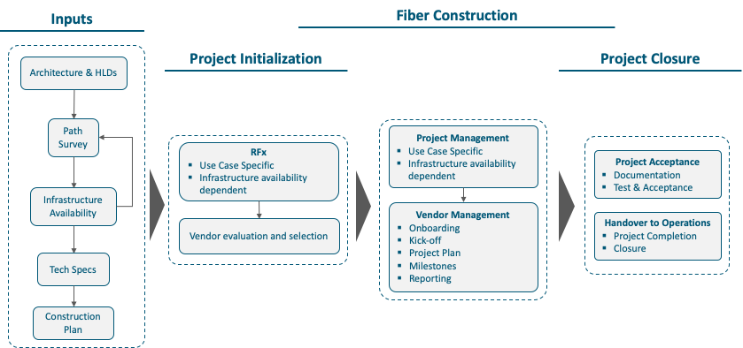
Figure 2. Site Construction Module Framework
2 Overview of Fiber Construction Management Process Flow
The fiber construction project commences with a Fiber Optic Path Design, as defined in the TX Network HLD Module, where a number of alternatives are evaluated for feasibility. During this initial assessment, synergies with existing infrastructures must be identified and the possibility of exploiting rights of way (ROW) must be analyzed.
Afterwards, a survey process confirms the optimal construction technique for each network span. Initial evaluation of terrain, infrastructure and crossings are documented during this phase, leading to a detailed implementation design and the specification of technical requirements, which triggers the construction plan.
Vendor selection and onboarding is the next step once the detailed plan is in place and the NaaS Operator has settled the criteria for vendor selection.
During the construction process, standard project management techniques shall be tailored to the specifics of this kind of project, setting intermediate milestones and phasing the implementation and delivery of each section of the network infrastructure.
Finally, a testing and acceptance process will ensure an adequate handover to operations and the commercial activation of the network.
2.1 Design and Requirements
The Fiber Optic Path Design has a significant impact on the development of the construction effort; a careful design, where potential issues and possible synergies are identified at an early stage will reduce the need for rework during the detailed design phase, prior to construction commencement. Details on this design process are provided in the TX Network HLD Module and the TX Network LLD Module.
The other relevant input to the construction project is the Technical Specifications, which describe the techniques that can be used to build the optical network infrastructure under different scenarios. These specifications are provided in the Fiber Construction Technical Specifications Template. A discussion on the selection of the construction technique is provided in section 3.2.1.
2.2 RFx Vendor Selection
The NaaS Operator will use the Fiber Optic Path Design and the Technical Specifications to set forth the requirements to select a construction partner.
An (optional) RFI (Request for Information) process may request the market for information on the construction options to complete the fiber infrastructure, while an RFP (Request for Proposals) process will request the invited construction partners for technical and commercial proposals which will be evaluated to select a construction vendor.
2.3 Project Management
Across all the project phases, but especially during the construction part, different project management techniques must be developed to establish the project scope, tracking methodology, responsibilities and delivery times for interim milestones and the complete construction work. Section 5 in this module provides references to the management tasks specific to a Fiber Construction project.
2.4 Test and Acceptance
As the final step on the construction management process, the testing and acceptance phase will ensure that the infrastructure has been delivered according to the specification and is ready for handover to operations for the subsequent commercial activation of the network. These tests will ensure alignment between the Construction Plan and the As-Built infrastructure through the review of documentation, drawings and in-the-field inspections.
Section 6 provides examples of the Test and Acceptance procedures applicable to a Fiber Construction project.
3 Design and Requirements
The Fiber Optic Path Design discussed in the TX Network HLD Module process intends to resolve a connectivity need, where the terrain and environmental conditions may impose limitations and constraints to the feasibility of the design.
Several design considerations will have a direct impact to the construction process, such as the Network Domain, the Deployment Scenario (greenfield or brownfield), and the Optical Services intended for the network.
The resulting design is completed with the Technical Specifications to produce a Construction Plan, which is the document that describes the construction activities, their dependences and the implementation requirements. The Construction Plan is the technical input to the vendor selection process.
3.1 Deployment Scenarios
It is known that the hierarchical organization of the physical infrastructure deployed by utilities (e.g. water, power, gas) is very similar to the fiber network architecture. Similarly, the paths followed by roads and railways connect the localities where network locations are placed. Therefore, the Fiber Optic Path Design must seriously consider the reuse of existing infrastructures to minimize the cost of fiber network deployment. This is defined in this document as a Brownfield Scenario for construction. On the other hand, if no utilities or infrastructure are available along the designed fiber route, a Greenfield Scenario for construction is considered, meaning that all construction needs to be performed from scratch, with no reuse of existing facilities.
In both cases, Rights of Way (ROW) are required; in a Brownfield Scenario agreement must be established with the owner of the infrastructure to set the terms and conditions of the shared use. In the Greenfield Scenario, permissions to cross different properties or to deploy fiber along roads will be required before construction commences. In case the required permissions cannot be acquired, the optical route must go through a re-design process.
3.1.1 Network Domains: Long-haul and Local Access
In the Local Access, enterprise or residential customers are typically connected using a hub-and-spoke or tree topology to an aggregation location. Point-to-point or PON (Passive Optical Network) technologies are increasingly the technology of choice on such topologies. These scenarios are prone to suffer more incidences; thus, the design aims to simplify the maintenance and facilitate a faster roll-out in case of fiber cuts or other issues. Figure 3 below depicts the typical domains (Local Access, Backhaul and Backbone) from a telecom network. The construction management of Local Access networks is out of the scope of this document.
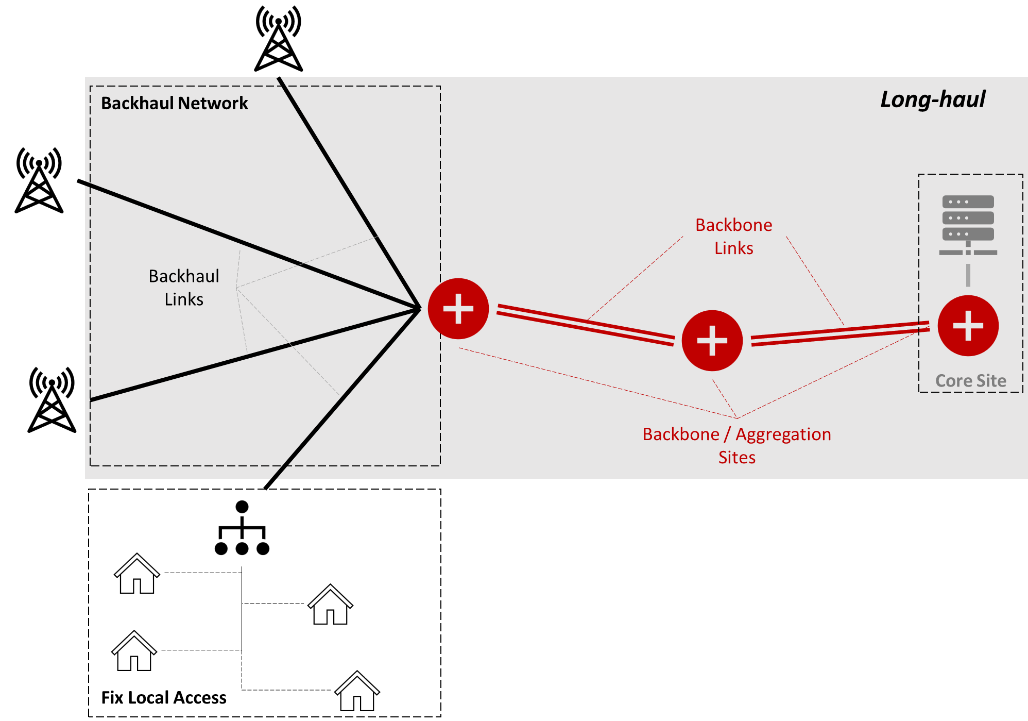
Figure 3. Network Domains
Under the Long-haul denomination, a distinction is made between Backhaul and Backbone. Backhaul links connect base stations to the aggregation points, typically established over relatively short spans (<10km), with a low number of fibers per connection, typically between 4 and 8.
The Backbone connects multiple aggregation points between each other and to the Core sites, oftentimes located at different localities. As such, it runs over longer distances and with higher capacity requirements than backhaul. Backbone cables are equipped with a larger number of fibers and may implement route protection, deployed in twin cables on independent infrastructures running in parallel; the use of such protection techniques would be specified during the Fiber Optic Path Design phase described in the TX Network HLD module. Cables with 12 to 32 fibers are typical in the backbone because the incremental cost of adding additional fibers during the construction process is minimal, while it provides increased resiliency in the case of a fiber failure and also enable the NaaS Operator to lease or rent spare fibers to other customers, monetizing the infrastructure investment.
Table 1 below compares the key attributes of the backhaul and backbone scenarios and can be taken by the NaaS Operator to identify their applicable scenario.
|
Domain |
Endpoints |
Distance |
Topology |
Fibers / Cable |
|
Backhaul |
Base Stations to aggregation points |
1-10 km |
P2P |
4-8 |
|
Backbone |
Aggregation points to each other |
10 -100 Km |
P2P |
12-32 |
Table 1. Long-haul Domains
The network domain being served by the optical infrastructure is therefore an important input to the construction process, as it imposes specific requirements and restrictions on the cabling, its supporting infrastructure, the protection mechanisms, and the fiber path.
3.1.2 Greenfield vs Brownfield
Civil works form nearly 60% of the total cost of fiber construction projects. Up to 80-90% savings on these civil works can be obtained from reusing infrastructures from utilities, a very significatively impact on the total required investment. The NaaS Operator can materialize those savings in different ways, for both Greenfield (where utilities have not established their networks yet) and Brownfield (where there are operating utilities) areas.
In a Greenfield area, the NaaS Operator must approach the utilities and explore the possibility for a coordinated deployment. Utilities deploying their networks will dig trenches and lay pipes and ducts to provide their services. The same infrastructure can be used for simultaneously deploying a fiber network, resulting in very significant savings on the civil costs, when compared to a new, independent telecom deployments.
In a Brownfield area, an existing infrastructure can be reused to install fiber and therefore reduce the construction costs and the project duration. Sharing agreements in the form of elaborated Rights of Way must clearly establish responsibility demarcation in terms of ownership, access to the infrastructure and technical support. The owner of the property or the infrastructure may impose limitations to the access, or the activities being performed during installation and operation, and request compensation for the use of the property. A careful negotiation of rights of way will save the NaaS Operator from unexpected problems in the future. A template for the Right of Way agreement is provided in Easement and Right of Way Template.
Table 2 compares the two utility-sharing scenarios as a deployment opportunity together with the cost and time advantages they may provide to the construction effort.
|
Utility Sharing Scenario |
Opportunity |
Cost Advantage |
Time Advantage |
|
Greenfield |
Coordinated Deployment |
80% reduction on civil works |
None. Limited by utility construction |
|
Brownfield |
Reuse existing infrastructure |
No or little civil works. Infrastructure adaptation only |
Significant. Infrastructure already available |
Table 2. Greenfield and Brownfield Utility Sharing Scenarios
3.1.3 Optical Services: Carrier Ethernet Services & Passive WDM
The fundamental aspects of fiber optic technology design are discussed in the Primer on Fiber Optic Technologies Principles document. The reader should refer to such document for additional information.
The intended use of the network capacity determines whether the optical services will be transported over a single optical carrier or using multiple carriers (also known as lambdas which correspond to different optical frequencies) each of them modulated by a different signal. The use of multiple lambdas increases the effective capacity of the fiber optics connection, at the expense of requiring more complex equipment and optical fibers with specific characteristics. The use of multiple optical lambdas may also impose limitations on the maximum length of the optical route.
On routes longer than 80 100 km, aggregation sites should be inserted to avoid the need for optical line amplifiers (OLA) or regenerators while providing an additional access point to the optical infrastructure. This module assumes that no OLA nor regenerators are required in any optical route. The selection of the fiber type for the planned optical service is an input to the construction process as it defined the requirements to the cables that would need to be installed.
The G.652 fiber (and its evolution version G.657) is a low-cost fiber, standard and qualified for services that don’t require speed higher than 10Gbps with short-haul distances.
If the required bandwidth is higher than 10Gbps or there is a need to support longer distances with higher performance, G.655 provides a better solution. Cost can be 2x higher, but the savings on equipment to compensate dispersion effects in this usage environment pay for the investment.
For even higher bandwidths and longer spans G.654.E provides very good results. Fibers are again more expensive, but the additional expenditure gets compensated by the avoidance of OLAs or regenerators.
Table 3 shows the Optical services and applicability for each type of fiber and can be used by the NaaS Operator to define the fiber type for each span to be deployed. The use of G.655 is recommended considering that it is expected that demand will increase through the time in service of the fiber (~20 years). The incremental cost compared to G.652 is marginal considering that the alternative is to redeploy new fiber or install additional and expensive electronics to allocate more capacity on G.652; however, if only P2P Ethernet services are foreseen and the NaaS Operator has tight budget constraints, G.652 can be selected. The use of G.654 should be limited to very high capacity or very long span scenarios.
|
Optical Service |
Fiber Type |
Transmission Window |
Applicability |
|
< 10Gbps, CWDM (Note 1), P2P Ethernet Short-haul (<100km) |
G.652.D |
1310 nm (zero dispersion) 1550 nm, 1625 nm |
Routes below 200km and low bit rates |
|
Up to 100Gbps, DWDM (Note 2) Long-haul (<200km) |
G.655 |
1550 nm (zero dispersion) 1625 nm |
Routes below 200km and high bit rates |
|
Up to 400G DWDM Long-haul (>200km) without OLA |
G.654.E |
1550 nm (zero dispersion) |
Long routes and high bit rates |
|
Note 1: CWDM: Coarse Wavelength Division Multiplexing. A wavelength multiplexing technique able to transmit up to 18 lambdas with a 20nm channel spacing. Note 2: DWDM: Dense Wavelength Division Multiplexing. A wavelength multiplexing technique significantly denser than C-WDM, carrying up to 160 lambdas with as little as 0,4 nm of channel spacing. |
|||
Table 3. Fiber selection per Optical Service.
3.2 Construction Planning Process
The Fiber Optic Path Design already described in the TX Network HLD module provides the input to the initial plan of the route through a Desktop Design, which consists on the analysis of the fiber optic path though topographic and land use maps, satellite images and any other indirect methods that do not imply visiting the path. This Desktop Design anticipates potential issues during construction and identifies the Rights of Way (ROW) which would have to be obtained.
The initial plan is then validated through on-the-field Surveys, which confirm feasibility of the planned route and the construction techniques which could be applicable. The Survey will also discover infrastructures not recorded in the Geospatial Database which could still be exploited during the construction process. The Survey Reports obtained from the field visits complement the Fiber Optic Path Design to produce a Construction Plan. A description of the components of the Survey Reports are provided in section 3.2.2.
The Construction Planning phase specifies the details of the physical infrastructure which will support the optical cables and host fiber access points where required for maintenance or interconnection, according to path design. The Construction Plan includes details not only on the civil works, but also on the cable installation technique and the interconnection to the route endpoints.
Figure 4 shows the activities within the Construction Planning Process, which are further developed in the following sections.
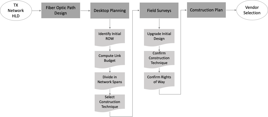
Figure 4. Construction Planning Process
3.2.1 Desktop Planning
The Fiber Optic Path Design received from the TX Network HLD module must be refined in preparation for the on-the-field Surveys. As part of the desktop planning, the first step is to calculate the Optical Link Budget for the complete path. The planned Optical Services will determine the fiber characteristics required for the link budget calculation. A detailed description of the Fiber Optic Link Design is provided in the TX Network LLD module.
3.2.1.1 Optical Link Budget Calculation
Optical loss budget analysis is the verification of a fiber optics operating characteristics. This encompasses items such as routing, circuit length, fiber type, number of connectors and splices and wavelengths of operation. The calculation is performed as described in the TX Network LLD module. In absence of fiber-specific values, the use of conservative defaults is advisable, as noted in Table 4:
|
Wavelength |
Attenuation / km |
Connector Loss |
Splice Loss |
|
1310 nm |
0.35 dB |
0.75 dB |
0.3 dB |
|
1550 nm |
0.22 dB |
0.75 dB |
0.3 dB |
Table 4. Default values for Link Budget Calculations
3.2.1.2 Network Span Identification
After link budget calculation, the design path is then divided in Network Spans, defined as portions of the optic path with similar construction characteristics. The terrain condition, the type of rights of way and the preferred construction technique establish the main attributes of the span.
The spans shall be limited to a maximum length that permits a full survey within a working day. Spans may be shorter if there are river or lake crossings, or if the construction technique varies because of the terrain or other access or legal restrictions. The use of other utilities along the path must also be considered when defining the span length. The recommended procedure for Fiber Optic Span Segmentation is described through the following steps:
Network spans are the construction unit for project management and infrastructure acceptance. They are defined to have homogeneous construction conditions across their length, so that progress can be easily monitored within each span and deviations from the planned construction progress rates can be easily detected.
Figure 5 represents a fiber optic path design segmentation in three spans; in the first span, the route runs along an area with low hills, finalized on a bridge crossing a river. The second span departs from the bridge and goes uphill through a high slope area, where several turns are required to reach the top of the hills. Span three is defined by a clear change in the terrain conditions, entering a flat area where the infrastructure can be more easily deployed.
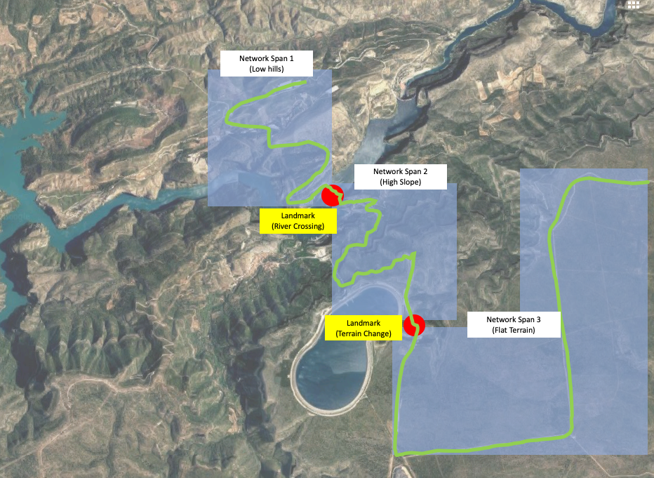
Figure 5. Network Span segmentation
Next, the construction technique for each span must be confirmed. Aerial cables are one of the most preferred and cost-effective solutions, because existing pole infrastructure can be easily reused without additional civil works. Additionally, aerial cable construction can be easily modified to add additional capacity.
However, aerial deployments are more susceptible to damage. The falling of tree branches, high winds or ice storms, vehicle accidents or the activity of animals can make the aerial cable strain or break.
Unlike the aerial deployment, buried fiber deployments are less susceptible to weather damage (mostly wind and ice, but also direct sunlight and dryness), which makes it often at least 10x more reliable than aerial routes, especially where severe weather conditions.
Table 5 provides a summarized comparison between the Aerial and Underground construction techniques. The NaaS operator must select one or the other depending on the specifics of the project. As a general rule, aerial deployment should be the selection of choice. Underground installations should be limited to areas where regulations or the security of the installation requires so, and always after a careful evaluation of the required budget. Details regarding construction techniques can be found in the Fiber Construction Technical Specifications Template.
|
Construction Type |
Relative Cost |
Reuse of existing infrastructure |
Ease to upgrade / modify |
Resiliency |
|
Aerial |
Low |
Simple |
High |
Low |
|
Underground |
Medium to High |
Only possible with ducts |
None Requires additional digging. |
High |
Table 5. Comparison of Construction Techniques
As an outcome of the desktop design phase, the NaaS operator shall obtain a preliminary design for the optical network, the supporting infrastructure, and a survey plan.
3.2.2 Survey
The span Survey consists of on-site verification of the planned design to detect potential problem areas and improvement opportunities before the construction work commences. The scope of the survey must be adapted to the planned type of installation, aerial or underground.
The execution of the Survey may be the scope of work of an independent RFx process, prior to the Construction RFP. In such case, the results of the survey would be inputs to the Construction RFP, providing additional scope insight to the construction vendors. As an alternative, the NaaS Operator may include the Survey into a turnkey project which includes the path analysis within the Construction RFP scope.
The general steps to complete the span Survey are the following:
After each survey, a Survey Form shall be delivered to the project manager. A Path Survey Report Template is provided to support this task. Instructions to use this form are provided below:
3.2.3 Construction Planning
The Construction Plan takes the initial Fiber Optic Path Design and the results of the span Surveys as inputs to produce detailed specifications and instructions for the execution of civil works on each network span.
On the Construction Plan, the NaaS Operator establishes the nominal conditions to the construction works, which will be implemented by the construction vendor. The steps to define the Construction Plan are summarized below:
The technical requirements are provided as part of the Runbook, in the Fiber Construction Technical Specifications Template. The Construction Plan, including such specifications, is used as the technical input to the Vendor Evaluation process.
The Construction Plan must be completed before the actual construction commences. This plan validates the timelines, establishes task dependencies and defines the supply chain that the vendor must establish for a smooth execution of the construction works. Fiber construction projects, especially when deploying long distances of fiber, are complex and require a high level of coordination within the construction team.
The development of the Construction Plan may be the scope of work of an independent RFx process, prior to the Construction RFP. In such case, the Construction Plan would be the primary input to the Construction RFP, providing additional scope insight to the construction vendors. As an alternative, the NaaS Operator may include the Construction Plan into a turnkey project which includes this step within the Construction RFP scope.
To deal with the project complexity in a systematic way, the Fiber Construction Gantt Diagram Template is provided which consists of an enumeration of the activities and dependencies involved in a fiber construction project. The systematization of the construction plan facilitates an early detection of deviations and permits comparison between the performance of the construction teams working on different routes.
The template consists of two sheets with different task breakdown for aerial and underground construction plans. The template user must set the start date of the first activity and the baseline duration of each task. All other dates shall automatically populate. The template assumes sequential completion of tasks, with no lag times or parallel activities. The user should modify these assumptions based on the specifics of each project. A template should be defined for each span, as the construction velocity may differ from span to span due to the construction and access specifics of each of them.
4 Vendor Evaluation and Selection
This section offers the NaaS operator a methodology and approach to select Vendors to provide Fiber Construction solutions and construction services.
The selection of the appropriate Vendors for Fiber construction projects requires conducting a RFI/RFP (request for information and proposal) process which analyzes the contractor ability to fulfill the end-to-end tasks and also obtains pricing information to fulfill the required Construction Solutions and Services.
Please note that the Fiber Construction RFI/RFP process benefits from the framework setup established in the generic RFx Process Module. It is recommended to go through the RFx process module if further details are required regarding the process. The RFx Process Module provides a general overview of the end-to-end RFx process including the description of the activities which take place for RFx development:
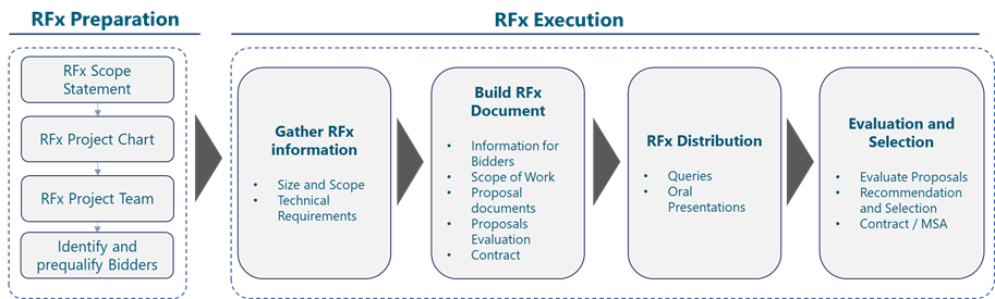
Figure 6. RFx Process
RFx are issued to obtain Information, Proposals or Quotes from the market. In order to obtain truly valuable and effective information from these processes, the documents generated during the RFx development must include all the relevant information that vendors will require to provide accurate responses to the NaaS Operator request, avoid misunderstandings and prevent implementation issues.
Before starting the RFI/RFP process, it is necessary to select the companies which will be receiving the documentation. The following sections provide instruction to select, invite and prequalify potential Bidders for the process.
4.1 Vendor Pre-qualification
The first step is to identify potential contractors to which the Fiber Construction RFx should be addressed, with an eventual invitation to bid. The Construction Management team must lead this process, with the technical assistance from the TX Design group on construction issues which could affect the optical transmission (e.g. bend radius, span length, fiber cable protection, etc).
The NaaS should invite vendors with previous and successful experience with the company and their competitors. In absence of previous references, options may include web research as well as requesting a list of Fiber Construction vendors to local partners and authorities, local Chambers of Commerce and professional associations.
The potential Respondents shall be sent an invitation letter, an abstract of the project scope and relevant RFx dates, and a set of questions to fill the prequalification form. This form provides key questions which the NaaS Operator will use to determine the suitability of the potential Respondent to address the project scope. This qualification form includes technical, commercial and legal questions with the objective to short-list the proper set of companies invited to the RFI/RFP process.
4.1.1 Invitation to Tender
The NaaS Operator shall submit an invitation to tender to the identified companies to inform about:
The objective of the formal invitation is to inform vendors of commencement of the RFx process.
4.1.2 Pre-qualification form
Potential Respondents shall receive, together with their invitation to bid, a prequalification form
The prequalification form responses shall be evaluated for pre-qualification according to the provided Fiber Construction Pre-qualification Template. This document identifies the main capabilities of the vendors, and discards those without the technical or financial capabilities to fulfill the project requirements.
The template consists of a number of questions about the vendor capabilities on different areas, such as Finance, Quality Management, CSR&EHS (Corporate Social Responsibility & Environment, Health and Safety) and OSP (Outside Plant) implementation experience. The questions come with predefined responses, typically compliant or non-compliant. The NaaS Operator will respond to the questions by selecting the option that better applies to the vendor under evaluation. The template will assign points based on those responses and will provide an overall score that can be used to rank the candidate vendors.
The prequalification form delivered to potential respondents should follow the Fiber Construction Pre-qualification Template, where the scoring calculations and notes shall be removed.
4.2 RFx Document
Having selected the candidate vendors through the pre-qualification process, the vendors shall enter an RFx process which is described in detail in the RFx Process module.
The RFx document identifies the RFx objective (obtain information, proposal and/or quotes), the scope of the technical project, the instructions to respond and applicable terms and conditions.
The Fiber Construction RFI/RFP Template provided as part of the PlayBook covers the areas in the RFx structure described above. This document must be adapted by the NaaS Operator to the fiber construction specifics of the project.
4.3 RFx Evaluation Process
The Fiber Construction RFI_RFP Template provides additional information on the inputs required to perform a response evaluation. Further details and general procedures on evaluation criteria are included in the RFx Management Module.
The evaluation process must be based on fair competition, with mandatory and optional requirements being clearly identified and properly notified to the bidders. The scoring model must be closed before the commencement of the analysis and, if by any reason it must be modified during the RFQ process, bidders must be notified and given the opportunity to amend their proposals.
The evaluation process as well is further developed in the RFx Process module and is considered out of the scope of this document.
5 Project Management
The design and delivery of the layers which comprise the network (civil infrastructure, cabling, optical connectivity and telecom services) is affected by bottom-up dependencies between these layers; cables cannot be deployed before the infrastructure is in place, and connectivity and services cannot be established until the fiber paths are established. This inter-dependency implies the need for a well-established set of processes which ensure the on-time availability of the pre-requisites for each layer. A Project Management organization must be defined for coordination and tracking of the multiple efforts which would converge on the delivery of the functional network at the end of the project.
As a result of the Planning process, a Project Plan shall be generated by the Contractor and agreed with the NaaS Operator. The Deployment Management Module provides guidance on establishing the general rules for project management on deployment projects. This section reviews specifics aspects applicable to Fiber Construction projects.
5.1 Vendor Management
Once the Fiber Construction vendor has been selected and the contract has been awarded and signed, the NaaS Operator will initiate a project and vendor management process through the execution of the construction works.
5.1.1 Vendor Onboarding
The construction project commences with vendor onboarding through a kick-off meeting. In this meeting, the NaaS Operator will explain in detail the project scope to the vendor representatives in charge of the construction process.
The Vendor Onboarding meeting agenda must cover all relevant aspects of the construction works, and serve to surface any pending clarification, doubt or concern from either the NaaS operator or the construction vendor in what refers to the construction work. Other subjects referring to non-technical issues (e.g. contractual terms, payment, insurances, etc) should be clarified in a separate meeting with the commercial and legal team.
A sample agenda for the kick-off meeting is provided below:
5.1.2 Project Planning
The Project Planning activity consists of developing the project management plan and all relevant project documents to establish the project scope of work necessary to achieve the project objectives. Project planning integrates all aspects necessary to execute the work required throughout the project lifecycle, including scope, time, costs, communication, quality, risk, and procurement.
The vendor shall develop a detailed description of the construction project by defining, for each network span and for the construction project as a whole, a Work Breakdown Structure (WBS) which subdivides the project deliverables and project work into smaller and more manageable components. Typically, these subdivides shall align with each network span or, when such spans are complex, the subdivide could be assigned to the use of different construction techniques or the consumption of certain rights of way or permits. In any case, the level of detail shall be agreed between the NaaS operator and the vendor, as it will establish the baseline for reporting and project tracking.
Within this WBS, all required activities shall be defined and sequenced based on expected dependencies. The vendor shall include estimates for the provisioning of any resources or materials required for the timely completion of each activity.
The Fiber Construction Gantt Diagram Template provides a sample Gantt diagram with an enumeration of the activities and dependencies involved in a fiber construction project that can be used as the starting point for a detailed WBS description.
5.1.3 Project Execution
The main task of the NaaS operator during project execution is to track, review, and regulate the progress to meet the objectives defined in the project management plan.
The Fiber Construction Project Tracking Template provides a template for project execution tracking, which should be updated by the Project Management Organization to enable precise control on the project execution activities.
The template includes several sheets where activity duration and milestones are set to establish the baseline and the actual values added to obtain a view of compliance with the project schedule. This template may be used for both individual spans and the aggregated fiber optic path, to track individual and overall progress.
Instructions on the usage of the template are provided below:
Instructions
This tab provides instructions on the usage of the template and the interpretation of the tracking milestones included in the template
Milestones
On this tab, the template provides the expected duration estimate between relevant milestones.
Fiber Tracking
On this tab, the template automatically populates baseline dates for each row (modeling a network span each) and provides space for the user to annotate the actual dates for each milestone.
Summary Tracking
This tab is used to compute the calculation that measures the discrepancy between the baseline and actual dates for each span. The user does not need to enter any data here.
Tracking Graphs
This tab graphically summarized the project progress, and the aggregated alignment with the project baseline.
Project execution reports will be oriented to control the current status of the infrastructure construction against the Baseline Timeline, defined in the Project Plan. Reporting will allow identifying and understanding deviations, informing on accomplishment of construction milestones and identification of risks potentially impacting the Project timeline.
To enable adequate control of the project, the NaaS Operator will define a project tracking methodology for vendor Management. Table 6 provides tools to assist in the process of controlling the project execution by the construction vendor.
|
Item |
Description |
|
Project Tracking File |
The Project Tracking File is a master Excel file containing the timing details required to develop tracking reports. This file includes main milestones and the comparison between planned and actual dates for each milestone. This Project Tracking Excel File could be replaced by a Project Management software solution which could be enhanced with an Inventory Solution. The Fiber Construction Project Tracking Template is provided to support control and status reporting of the Project.. |
|
Monthly Reports |
Excel and PowerPoint files providing a summarized view of the information from the Project Tracking File must be generated for review by the NaaS Operator. |
|
Weekly or Daily Report |
A frequent comparison between Baseline and actual dates enables early detection of deviations from the baseline and the implementation of corrective actions, as well as the impact of the overall project completion. |
Table 6. Tracking Aids
The Project Tracking File includes several milestones which identify the main construction events in the infrastructure building project. A brief description of each milestone is provided in the Instructions tab in the Fiber Construction Project Tracking Template. Table 7 below provides a more detailed definition of each milestone for the users reference:
|
Milestone |
Description |
|
Technical Path Survey Ready |
After the Technical Site Survey has been completed, the construction vendor is responsible to deliver the Technical Path Survey Report, which serves as main input to the detail planning of the fiber span design. |
|
Path Engineering Document Ready |
Generation of construction engineering document, describing technical solution and implementation plan |
|
Path Construction Work Order Ready |
Fiber Construction Order is released by NaaS Operators to authorize the commencement of construction works. Approval of engineering plan and GO confirmation received (materials available, construction ready to commence) |
|
Civil Works completed |
This Milestone will indicate the finalization of Construction Works (pole planting, underground burial, trenching). The physical infrastructure is ready for the installation of mechanical elements to support optical cables. |
|
Mechanical Works Completed |
Additional mechanical works (installation of pole stays and supports, laying of ducts, trench compaction and backfilling) is completed. The infrastructure is ready to receive the optical cables. |
|
Cabling Works Completed |
The installation of cables (via messenger wires, ADSS [All Dielectric Self Supporting Cable] aerial cables, blowing into ducts, etc) and cable tensioning is completed. The installation is ready for self-inspection. |
|
Path Construction Acceptance |
Infrastructure has passed self-acceptance by the vendor. The acceptance process follows the testing guidelines in section 6, which includes the use of specialized equipment such as an optical time domain reflectometer (OTDR). The NaaS Operator has been notified and has executed Civil Engineering Acceptance and issued a Path Construction Acceptance if any item needs to be repaired. The NaaS Operator verifies the fiber infrastructure against a construction checklist. The Fiber Construction Acceptance Checklist Template provides a template for such acceptance form. This template is extracted from the construction technical specifications, since they are the requirements for the construction works. By review of the checklist items, the NaaS Operator provides a punchlist with the construction items that need amendment before issuing the final acceptance. |
|
Ready for Operation |
Optical fiber post-install testing has passed self-acceptance. Vendor has fixed all the items in the Punchlist. The NaaS Operator has been notified and final acceptance has been scheduled. |
|
Path in Operation |
All fiber fusions confirmed. Cable is connecting network endpoints, and ready for commercial operation. The NaaS Operator has accepted the fiber infrastructure. |
Table 7. Fiber Construction Milestones
5.1.4 Project Closing
The Project Closing phase consists of executing the processes necessary to finalize all activities and formally complete the construction project and associated contractual obligations. These processes are summarized in the procedure below:
5.2 Quality Assurance
The construction vendor must establish quality management procedures in conjunction with the NaaS Operator to ensure that installation, equipment, material and workmanship conform to the standards required in the contract documents. The construction vendor must submit a Quality Assurance Plan as part of the construction project plan for review and approval by the NaaS Operator before the commencement of the agreement.
The text below summarized the minimal content of the Quality Assurance Plan request to the construction vendor. The goal of this document is to obtain confirmation from the vendor, via experience and certifications, that the construction works can be executed in alignment with industry standards and applicable regulations.
Below, generic Quality Assurance requirements that Constructions vendors must comply with are listed:
6 Test and Acceptance
This section provides a high-level description of the Acceptance Process to be applied for the deployment of the fiber network. The main objective of the Acceptance Process is to provide a framework to be followed for the formal acceptance of the network elements.
6.1 General Acceptance Process
Practical fiber optics testing implies testing each cable for continuity before installation, to ensure there has been no damage to the cable during shipment and testing each segment as it is terminated. Finally, the entire cable run is tested for end-to-end loss.
All testing activities fall under the responsibility of the construction vendor. The NaaS operator shall review the test results and may request specific testing on any network span to confirm the measurements taken by the vendor, as part of the final acceptance process. The Fiber Construction Acceptance Checklist Template for information on the acceptance process checklist. The contents of this checklist are described below:
6.2 Pre-Installation Tests
Construction vendors need to comply with industry standards in pre-testing the fiber prior to installation to ensure that the losses due to laying/blowing the fiber are within accepted tolerances. In particular:
Fiber characterization can be defined as the field measurement and recording of fiber span parameters that affect signal transmission over all or selected operating wavelengths.
Even though the characterization parameters are available from fiber cable specification sheets, during transport and after cable installation they can change significantly. Besides, cable spans can be made up of numerous (and potentially different) concatenated fiber types which makes it difficult to calculate the total span parameter from individual cable section specifications.
Table 8 helps in determining which key parameters need to be considered when deploying various transmission systems. Some of these parameters, such as Fiber Loss, Chromatic Dispersion (CD), Polarization Mode Dispersion (PMD) and Return Loss (RTL) can be measured on a single-ended configuration, without the need to inject traffic into the fiber with a receiver at the other side. Single-ended measurements are considered mandatory.
Dual-ended measurements, such as Optical Signal to Noise Ratio (OSNR) and Bit Error Rate (BER) are regarded as optional and can be deferred until the fiber is put in service.
|
TX System |
Loss |
CD |
PMD |
RTL |
OSNR (optional) |
BER (optional) |
|
< 1Gbps |
x |
– |
– |
laser |
– |
x |
|
1 5 Gbps |
x |
– |
– |
x |
– |
x |
|
> 10Gbps |
x |
x |
x |
x |
– |
x |
|
WDM Passive |
x |
> 10G |
> 10G |
x |
– |
x |
|
Overall Span Quality |
x |
x |
x |
x |
x |
x |
Table 8. Recommended parameters for Fiber Characterization
Fiber characterization is performed before and after new fiber cable link construction following the process and considerations described below:
6.3 Post-Installation Tests
The construction vendor must verify each fiber span after install, and the complete end to end installation when finalized. For each infrastructure span, the General Acceptance Process will consider the following components:
The Naas Operator must establish a self-acceptance regime with the construction vendor. Under this model, the construction vendor will perform the testing for each span and present the results to the NaaS Operator. The contractor will provide an acceptance plan timeline before and after the acceptance events, which will include specific reports for elements which have failed tests and the corrective actions mandated to amend the detected defects. A representative from the NaaS Operator may be present during testing, but this won’t be mandatory.
The construction vendor must provide all equipment, technicians, supplies and any other items required for conducting the acceptance tests. The contractor is also responsible to guarantee that the required scenario for the acceptance tests is available and operative.
6.4 Definition of acceptance requirements
This section describes the testing procedures that shall be carried out by the construction vendor prior to the NaaS Operator accepting the infrastructure. As stated above, the Construction Acceptance process is based on the self-acceptance of the infrastructure components by the construction vendor before presenting to the NaaS operator for final acceptance. The procedures described below will be discussed and agreed with the construction vendor, so that acceptance test protocols are developed and applied each time a network section is completed.
6.5 Documentation and Inventory
The Project documentation, including the as-built drawings, element specifications, and acceptance test protocols (ATP) shall be stored in a cloud repository, according to a folder structure which facilitates document classification and query. The use of commercial or opensource Document Management System or Enterprise Content Management (e.g. Google Drive, Microsoft OneDrive, and Alfresco ECM) is highly recommended, as standalone or in coordination with a GIS inventory.
The information made available for storage and inventory shall be according to the following considerations:
6.6 Network Infrastructure Operation and Maintenance Documentation
Once the infrastructure is completely accepted and the documentation delivered to the NaaS Operator, the Network Infrastructure Operation and Maintenance Guidelines must be established for commercial operation.
The Operations and Maintenance documentation must include, at least, the following items:
1. Site Construction Management Introduction
The Site Construction Management Module provides the NaaS Operator with background information and methodologies to go through the Site Construction process. It starts providing an overview of the Construction process, including a step approach which starts with the Technical Site Survey, Architectural and Engineering Analysis, and continues with a review of the tasks in the civil, electrical and mechanical construction areas. The module continues with a review of all construction components including primary support structures, equipment cabinets or shelters, cable management facilities, antenna mounting structures and power supply, grounding and lightning construction components.
Construction services from 3rd Parties need also to be considered for Site Construction. The Site Construction Module creates awareness of such Site Construction services and provides NaaS operators with the tools for requesting, evaluating and selecting partners to execute these services. Finally, the module addresses the management of Site Construction Vendors as they go through the construction execution phase.
1.1 Module Objectives
The Site Construction module will enable a NaaS Operator to manage the construction of RAN sites. The module has the following specific objectives:
1.2 Module Framework
NaaS Runbooks Framework shown in Figure 1 displays the PlayBook Modules and their relationship to Site Construction Management.
Strategic Plan & Scope and High-Level Network Architecture drive the strategic decisions to forthcoming phases. Deployment is the second step in the implementation strategy, and the same as other modules, it is supported by Supply Chain Management.
The Site Construction Management module is included within the Deployment stream. Within this stream, Site Construction Management Module has a direct relation with Site Survey Module which constitutes a relevant input to determine the specific Site solutions. Site Construction Management also takes inputs from Network Design Modules including Civil & Power Design Module.
Site Construction Management Module provides NaaS operators with guidelines for evaluation and selection as well as management of Site Construction Vendors
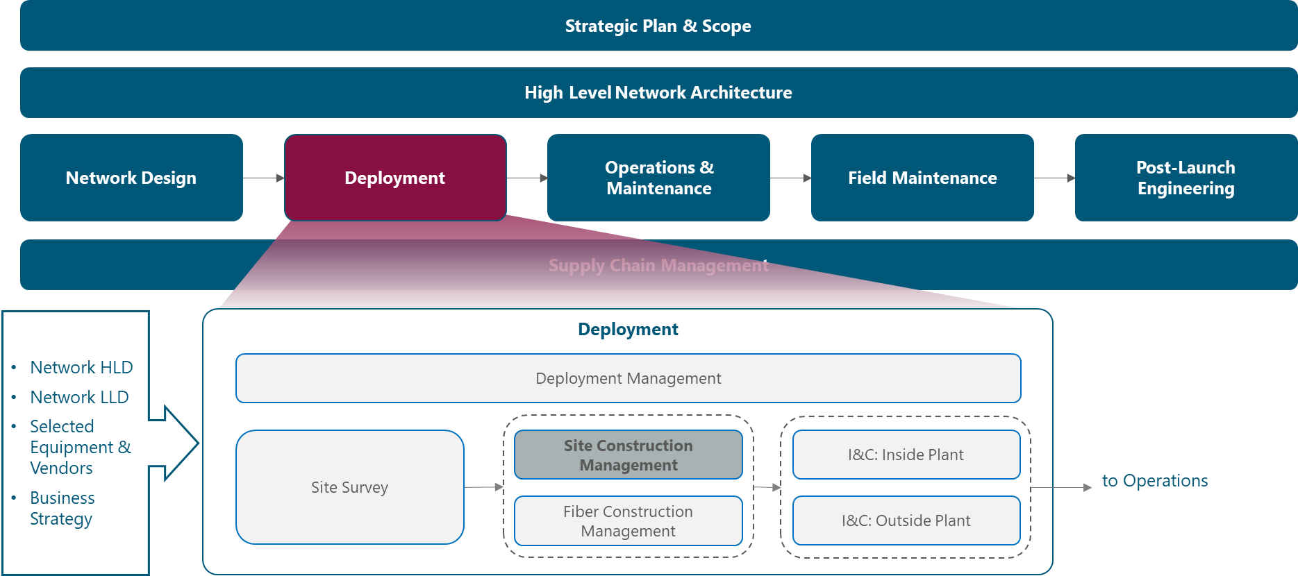
Figure 1. Module Framework
Figure 2 presents the Site Construction Management functional view where the main functional components are exhibited:
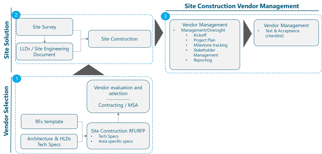
Figure 2. Site Construction Module Framework
The rest of the module is divided into four sections. Section 2 is an overview of the Site Construction Management end-to-end process. Section 3 provides a more detailed description of the construction components necessary to better understand the design of the specific Site solutions. Section 4 details the process to select Site Construction partners that will execute the construction activities required by the NaaS Operator. Finally, Section 5 addresses the management of Site Construction Vendors, including the description of reporting, documentation, and acceptance requirements.
2 Site Construction Process Overview
Figure 3 shows an overview of the Site Construction process, showing in green color the tasks which involve Construction Teams (tasks which usually will be outsourced to Site Construction Vendors):

Figure 3. Site Construction Process Overview
Understanding the Site Construction flow will help a NaaS Operator manage the end-to-end set of construction activities and will help them to better describe the requirements to be included in the RFx processes for selecting partners for Construction.
This section describes the Construction activities starting with Technical Site Survey, which will be followed when required by an Architectural and Engineering analysis of the site solution and then the generation of the Site Engineering document. These pre-construction activities will be followed by construction activities which are divided into Civil, Electrical and Mechanical works. Once Civil works and Electrical and Mechanical works have been finalized, the Site will be ready for Construction Acceptance before proceeding with Network Equipment Installation which is addressed in the I&C Module
Table 1 provides a high level view of responsibilities between main stakeholders involved in Site Construction in a NaaS environment (some variations may occur depending of specifics of the NaaS operational model):
|
Construction Area |
Construction Task |
Responsible |
|
Site Survey |
Carry out Site Survey |
Constr. Partner or TowerCo + NaaS (optional) |
|
Generate Technical Site Survey Report |
Constr. Partner or TowerCo |
|
|
A&E Analysis |
Carry out Structural Analysis |
Constr. Partner or TowerCo |
|
Generate Site Engineering Document |
Constr. Partner or TowerCo |
|
|
Validation |
Validate Site Solution |
NaaS Operator |
|
Civil Works |
Preparation |
Constr. Partner or TowerCo |
|
Foundations |
Constr. Partner or TowerCo |
|
|
Mechanical & Electrical |
Mechanical Construction Component |
Constr. Partner or TowerCo |
|
Electrical Construction Component |
Constr. Partner or TowerCo |
|
|
Acceptance |
Construction Acceptance |
NaaS Operator |
Table 1. Site Construction Responsibilities.
2.1 Technical Site Survey
The Objective of the Technical Site Survey task is to determine the suitability of the proposed location to accomplish with engineering objectives. During the Technical Site Survey, the Construction team needs to determine the most suitable construction site solution and gather all the information which will allow a later engineering analysis and the generation of the Site Engineering document.
The output of the Technical Site Survey is the Technical Site Survey Report, which includes information about the new structure to be built or the existing structure to be adapted. Technical Site Survey Report can also include space analysis, power supply analysis as well as drawings and photos which will allow a later post processing to carry out structural analysis and generate the Site Engineering document.
The Site Survey process is schematized in Figure 4:
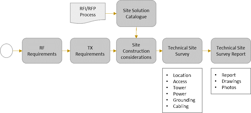
Figure 4. Site Survey Process
For more detailed information about the Site Survey activities, please refer to Site Survey Module, which is also part of the Deployment area as introduced in section 1.2.
For more information please review the Site Survey Module, which offers a guideline to help NaaS Operators to determine the resources who should be performing the Technical Site Survey in a Rural Environment.
NaaS Operator can use the provided Technical Site Survey template (template A) to record the information collected through the Technical Site Survey activities.
2.2 Architectural and Engineering Analysis
The main objective of the Architectural and Engineering analysis is to perform the structural analysis and validate the solution selected after the Technical Site Survey.
This analysis is important to certify that the supporting structure to be installed or re-utilized will be able to support the load that is being planned to be mounted on the tower/building. The NaaS Operator and/or the construction Vendor will be legally responsible for ensuring the safety of the site from a structural point of view and therefore the structural analysis is critical to avoid the possible collapse of the structure mainly due to wind.
Structural Analysis consists of the tower load analysis subject to components load (i.e. all the equipment which will be installed in the tower), as well as terrain characteristics (i.e. geotechnical information, which will also consider wind, ice and seismic characteristics). Tower Load will impact the tower foundation requirements which will be specified in the Site Engineering document.
Here, it is important to differentiate between New Sites (Greenfield or Build to Suit) or Existing Sites, since this will impact on the necessity to perform a Structural Analysis for the Site Construction. The process to determine this need is summarized in the schema from Figure 5.
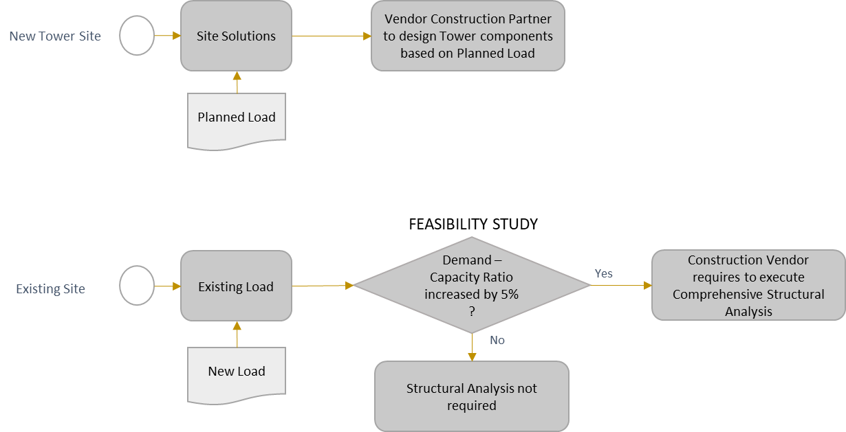
Figure 5. Site Engineering Analysis
After this Engineering Validation has been performed, CAD (Computer Aided Design) tools are used to generate the Site Engineering document.
Site Engineering Document contains detailed blueprints corresponding to each specific Site deployment. NaaS operators can include this service in the Managed Services contract with Construction partners or could use internal resources and available tools like FreeCad to produce Site Engineering documentation with the required detail level. Samples of a Site Engineering document are provided in Figure 6, Figure 7 and Figure 8.

Figure 6. Site Engineering Sample 1

Figure 7. Site Engineering Sample 2
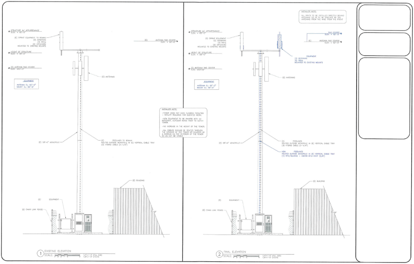
Figure 8. Site Engineering Sample 3
2.2.1 Tower Loading and Foundation Guidelines
NaaS operator will rely on Site Construction Partners to certify that the design of the tower is in accordance with the planned tower load. Tower Load will impact the tower foundation requirements.
It is important however to highlight some considerations to be taken into account when making the requirements for this activity to the Site Construction Vendor. These guidelines will also constitute a good reference for NaaS Operator Construction team for reviewing and assessing the work of the Site Construction Partner.
Dead Tower Load considers the weight of the tower structure as well as antennas, antenna mounts, transmission lines, conduits, lightning equipment, climbing devices, platforms, signs, anti-climbing devices, etc.
Besides Dead Tower Load, Wind Loading is the predominant dynamic loading to be considered outside dead weights. The following guidelines are applicable:
Most appropriate foundation type depends on several factors included the loads that may be able to support, the soil conditions as well as the cost.
Engineering will consider the following steps when designing the tower foundation:
Foundation design for towers and equipment cabinets or shelters must be based upon site soil conditions as noted in the geotechnical report. These foundation plans must be designed by a licensed Professional Engineer and the design must be included in the Site Engineering document.
A Professional Engineer or contracting firm should determine whether the soil is adequate to properly support the concrete foundation or slab. The Professional Engineer or contracting firm should determine the excavation depth and the required fill, if required.
Foundation design should consider any precipitation conditions unique to the location. These considerations include (but are not limited to) elevated (pier type) platforms used in low-lying areas prone to regular flooding, and elevated foundations used to prevent burial of site due to snowfall.
All foundation construction must be performed by a qualified contractor specializing in this work.
Vendor Construction Partner will provide information about applicable Standards followed for the tower load design. Some of these standards are listed in Table 3.
|
Standard |
Standard owner |
|
TIA/EIA-222-G [or higher] |
Telecommunications Industry Association/ Electronic Industry Alliance |
|
BS 8100-1: Lattice Towers and Masts – Part 1: Code of Practice for Loading |
British Standard Institution (BSI) |
|
BS EN 1993-3-1:2006: Eurocode 3. Design of steel structures. Towers, masts and chimneys. Towers and masts |
British Standard Institution (BSI) / European Union |
|
ASCE 10-97: Design of Latticed Steel Transmission Structures |
American Society of Civil Engineers |
|
AS 3995-1994: Design of steel lattice towers and masts |
Standards Australia |
|
BS EN 1992-1-1:2004+A1:2014: Eurocode 2: Design of concrete structures. General rules and rules for buildings |
British Standard Institution (BSI) / European Union |
Table 3. Tower Load Standards.
2.3 Civil Works
After the Site Engineering document has been produced and validated, the Site permits have been obtained and a Purchase Order has been issued to the Site Construction Vendor, Site Construction can start. Site Construction begins with Civil Works, which main tasks are depicted in the following figure:
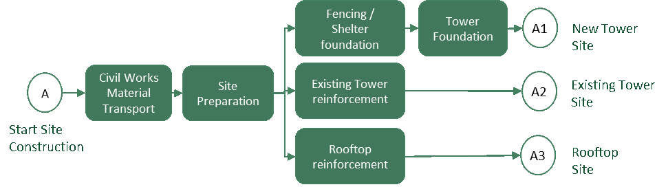
Figure 9. Civil Works in Site Construction
The following paragraphs provide an instructional step approach for the tasks to be executed. The main objective is to provide NaaS operators with a description of the set of civil work activities to be implemented. Understanding the process will support a NaaS operator with the required background to track the execution of construction process tasks.
2.3.1 Civil Works Material Transport
Material required for Civil works needs to be transported to the Site Location. Civil Work Materials will include among others the following:
Machinery for drilling (required for monopole towers and anchors) and excavating the site foundation required area(s).
Machinery for concreting and backfilling the site foundation area.
Rebar cages and frames to be lifted into drilled holes and/or foundation pads for concrete reinforcement.
Concrete
Water
Arid materials: sands and existing gravels
Other component authorized by Contractors Civil Works Manager
Machinery (cranes or alternatively pulley or winches for lighter structures) for lifting the tower and the shelter (if necessary)
It is relevant to mention here that Construction Vendor must utilize materials from a materials list which complies with construction standards and country normative to avoid future operational costs in maintenance activities. The Contractors Civil Works Manager will be responsible to guarantee that utilized materials are compliant with standards.
2.3.2 Site Preparation
The input for Site Preparation will be the Site Design documents (i.e. Site Engineering document) and the output of the activity will be an area prepared for concrete pouring.
Site Preparation will include the following subtasks:
2.3.3 Complete Tower and Shelter Foundation structure
Once the Site is prepared, the next step consists of implementing the complete foundation required for tower and cabinets/shelters erection. Depending on the Site Design (which will have considered the characteristics of the equipment shelter), the use of metallic platforms or concrete bedplates to isolate and protect the cabinet will be required. On the extreme side, if all the equipment is held by the tower, there will be no need for such a Shelter Foundation.
Foundation will include the following main subtasks:
2.3.4 Existing Tower reinforcement
If the Site is going to be deployed in an existing tower infrastructure, this structure might require to be reinforced to support the added weight by yje new equipment and new antennas. As it has been described in the Architectural and Engineering Analysis section (section 2.2), a feasibility study will be performed to determine if this is required.
The areas which commonly require reinforcement are the tower base, the tower shaft or axis and the tower junctions (in case the tower is formed by several welded or bolded sections). In exceptional cases it might be required to increase or reinforce the foundation area.
Tower reinforcement actions might include:
Reinforcement of Tower Base section by using Base flanges.
Reinforcement in some sections of the shaft by using bolted plates and/or pole savers
Reinforcement of tower junction sections using welded flanges, sleeves or bolts
2.3.5 Rooftop reinforcement
When deploying the site on a rooftop, it will be required to ensure that the load is distributed on columns or beams of the building. Depending on the load of the equipment shelter, this may require the usage of platforms or transition structures to allow an adequate load distribution.
In the case a small tower or structure is required to hold the antenna system, some solutions are possible including tower counterweights, tripod structures (anchoring the main pole to a building column and using legs anchored to beams or directly on the floor).
2.4 Mechanical and Electrical Works
This section will provide a step approach allowing the overview of the mechanical and electrical works which are required after Civil Works have been completed.
This step approach will allow a NaaS operator to have an understanding of the activities, facilitating the tracking of their execution, which will usually be undertaken by the selected Construction Vendor. The main areas in which these works are grouped are highlighted in the following figure:
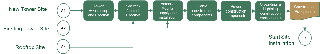
Figure 10. Mechanical and Electrical Works in Site Construction
2.4.1 Tower Assembly and Tower and Shelter erection
2.4.2 Antenna mounts supply and installation
Antenna and accessories mounts are supporting structures that allow to securely attach these elements (antennas, transport equipment and other accessories) to the main primary structure (tower, rooftop) and prevent their movement in high wind conditions.
Antenna and accessories mounting structures include platforms, arms, clamp rings, frames, pipes and other ad-hoc mounting structures.
For tower sites, most of the time these mounting structures will be bolted, clamped or chained to the tower structure.
For rooftop sites, frame structures and roof mounts for antennas will be installed using counterweights or tripod structures. Wall mounted poles and brackets will be used for individual antenna installations.
Examples of such construction components can be found in section Antenna Mounting Structures (section 3.1.2).

Figure 11. Safety climbing systems (step bolts, ladder) components
Safety climbing systems are usually already integrated with the tower structure. In the case any type of final work (tower sections assembling, attachment of antenna and equipment mounting structures) was required, these works should be done on ground.
2.4.3 Cable management
Cable management construction components prevent cables from become damaged due to weather conditions (wind, ice) or during maintenance work on the tower.
Cable management components are required to manage different type of cabling necessities:
In the case of tower structures, these components usually consist of cable ladders and hangers which will be attached to tower sections while on the ground to avoid air work activities.
In the case of rooftops, hangers, cable ladders and waveguides will be installed usually attached to rooftop floors and walls. If required, suspending levers will be utilized to allow aerial installation of ladders and waveguides.
Detailed information about cable management construction components and guidelines for their installation can be found in section Cable management construction components (section 3.2).
2.4.4 Power Construction
Power construction activities are required to provide power infrastructure required by radio and transmission equipment, as well as by all site auxiliary elements requiring power.
Radio and Transmission equipment will usually work with DC (-48V or +24V), requiring the power system to be equipped with AC-DC rectifiers if AC grid power is utilized in order to convert the alternating current (AC) to direct current (DC). Alternatives to grid power includes the use of solar panels or diesel generators (although this last option should be avoided if possible due to high maintenance costs).
When grid power is utilized, Power Construction activities will include (variations may be considered to follow specific country regulations):
2.4.5 Grounding and Lightning
Towers are structures with a high risk of lightning strike and therefore require grounding and lightning protection systems. The essential function of a grounding and lightning protection system is to prevent a lightning strike damaging the structures and equipment. This is achieved by diverting the strike energy to the ground before it gets into the equipment room.
Grounding network must accomplish all normative and regulations for the structures utilized in the Site. All metallic parts of the site will be grounded, using isolated conductors connected by the grounding system to the grounding rods.
Grounding Cable Routes must use the shortest possible route for grounding cables and with the fewer possible curves. Lightning rod will be used on top of the tower when necessary. Lightning rods will be able to attract lightning strikes and flow the lightning current through the tower grounding system. They are necessary if the structure represents a high point in the area (higher than surrounding objects) and this area has high probability of incidence lightning strikes.
Buss bars are construction components used to connect grounding cables from antennas and other locations to the main grounding cable. Buss Bar Kits must be installed minimally at the following locations (at their bottom side):
All the steel sections on the foundations that could have been built for the tower and the equipment cabinet/shelter must also be bonded to the grounding system, as well as the cabling management components (ladders and waveguides) from equipment to the antenna and equipment masts. If the equipment is hold on top of a metallic platform, this platform will also be grounded.
3 Site Construction Components and Guidelines
This section of the module contains descriptions and illustrations of Site Construction Components, as well as guidelines and best practices to be considered by Construction Partners and/or Construction teams of the NaaS Operator.
It will provide a good reference information and an input for the Construction Manager and the Site construction teams. This information will be relevant when defining the Site solutions which will be part of the deployment and which will be requested to Construction partners through the RFI/RFP processes.
Construction components include Towers (Primary structures), Antenna mounting structures, Cabling and Power Supply construction components, Equipment shelter construction components and Site Grounding and Lightning components.

3.1 Primary structure and antenna mounting structure
The section provides an overview of the primary supporting structures (towers, rooftops) and the secondary supporting structures (mounting structures used to attach antennas and other equipment to the primary structures).
3.1.1 Type of Primary Structures
Towers constitute the majority of primary supporting structures in rural areas, whereas rooftop mounts represent the majority of structures in the urban areas. The following are the main options for Primary Structures:
NaaS Operators will model the RAN Configurations as part of the RAN Low Level Design, that will specify among other things the required antenna height. Site Construction responsibilities will include the selection of the type of primary structures to be used for each RAN Configuration.
These Site Configurations will be determined by considering:
The Planned Site Configurations will be agreed and confirmed throughout the RFI/RFP process with potential Site Construction Vendors.
Table 4 assesses the Primary structures to be utilized in typical environments:
|
Scenario |
Primary Structure |
|
Urban |
● Rooftop with Rooftop antenna mounting structures |
|
Suburban and Rural |
● Monopole Towers: It will typically be chosen for small structures with a single pole of the desired height (Typically less than 20m) because of easy installation and reduced footprint. ● Self-supporting: If more than 20m are required, self-supporting towers will usually be chosen. ● Guyed towers: Used in rural scenarios when high towers are required (typically more than 60m) and there are no footprint restrictions. |
Table 4. Typical Primary Structures
Telecom towers and required Tower anchors will require foundations for their installation. NaaS Operator will usually rely on Site Construction Vendors for the design of such foundations. For NaaS Construction team reference purposes, a Primer for Construction Guidelines for Tower Foundations and Anchors is provided.
The following sections contain descriptions and key characteristics of the main types of Primary Structures.
3.1.1.1 Monopole Tower or Post Mast
Monopole Towers or Post Masts are self-supporting towers which consist of a single vertical pole fixed into the ground and/or attached to a foundation. Depending on the height, it may also consist of a set of tapered steel tubes that fit over each other to form a stable pole.
Monopole Towers require less footprint and are perfect for small sites.
The main advantages of monopole towers are:
Main characteristics and guidelines for Monopole Towers
Table 5 contains the main characteristics of the Monopole Towers:
|
Main characteristics and guidelines for Monopole Tower or Post Masts |
|
Pipe diameter decreases from bottom to top |
|
A monopole tower should be fitted with climbing rungs where necessary. |
|
Monopoles are to be made from galvanized hollow steel pipes or high strength steel and designed for a variety of multi-user configurations and finishes to meet local aesthetic requirements. Zinc coating galvanizing helps prevent premature rust and corrosion. |
|
Each shaft section should be a constant-tapered hollow steel section |
|
The pipes shall be tapered to ensure that one pipe base fits into the top of another until the desired height is achieved. A joint in the arrangement should have an overlay between the two adjacent pipes. |
|
The depth of the overlay, the base width and the number of pipes in a particular monopole shall be determined by expected height of a tower, the thickness of the pipe walls, the base diameter and whether the tower shall be guyed or not. |
|
Foundation type: Drilled is the most common foundation type for Monopole Towers |
Table 5. Monopole Tower Guidelines
The following are descriptive pictures of Monopole Towers:
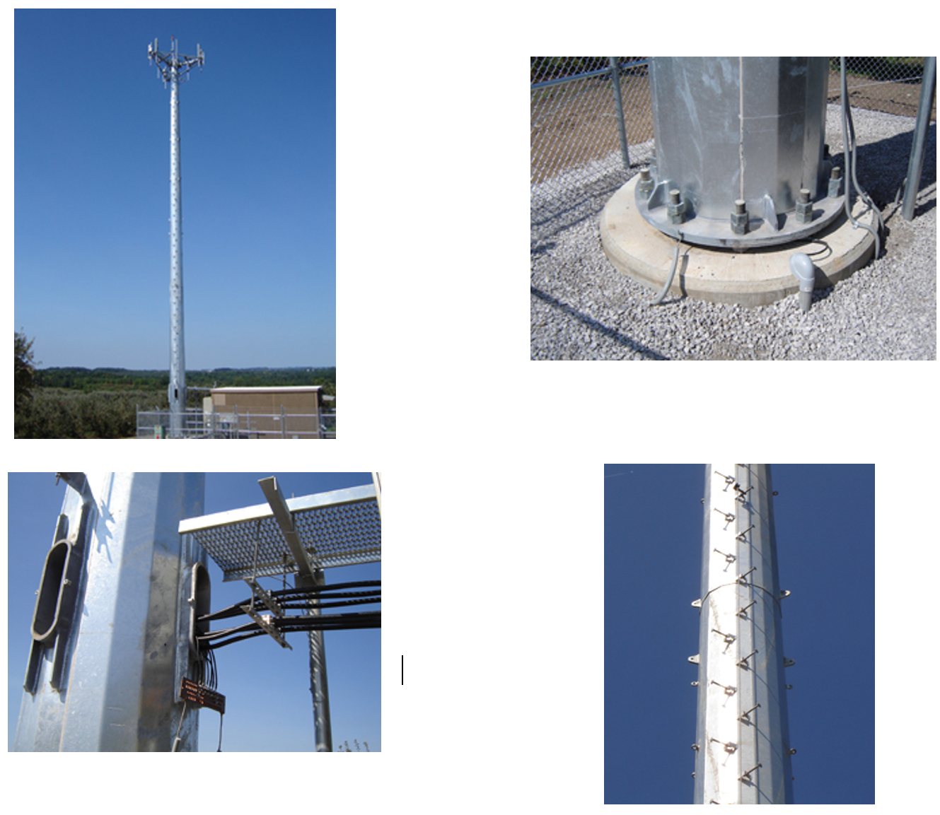
3.1.1.2 Self-supporting or Lattice Towers
Self-Supporting towers are free-standing lattice structures.
Self-support towers have a larger footprint than monopoles (it may require 10 times more space than a monopole tower, but can also reach 3 times the monopole height). Their footprint is usually much smaller than Guyed Towers footprint.
3-legged triangular based pattern is the most common. Angle or Pipe (tubular and solid) for the legs, assembled in sections including a latticework of cross braces bolted or welded designed for medium to heavy loads.
The main advantages of Lattice towers are:
Main characteristics and guidelines for Lattice Towers
Table 6 contains the main characteristics of the Lattice Towers:
|
Main characteristics and guidelines for Self-Supporting Tower (also known as Lattice Towers) |
|
Self-supporting towers shall be designed and constructed as lattice structures. |
|
Triangular or square structure |
|
Tube legs, angle legs, lattice legs or solid round legs. |
|
Face widths vary according to height and load capacity. |
|
Rest platforms provided every 20 meters of height. |
|
Work platforms provided also at heights where antennas are to be installed. |
|
Fitted with a climbing ladder. |
|
Foundation type: Standard (Pad) or Raft foundation |
Table 6. Self-Supporting Tower Guidelines.
The following are descriptive pictures of Lattice Towers:
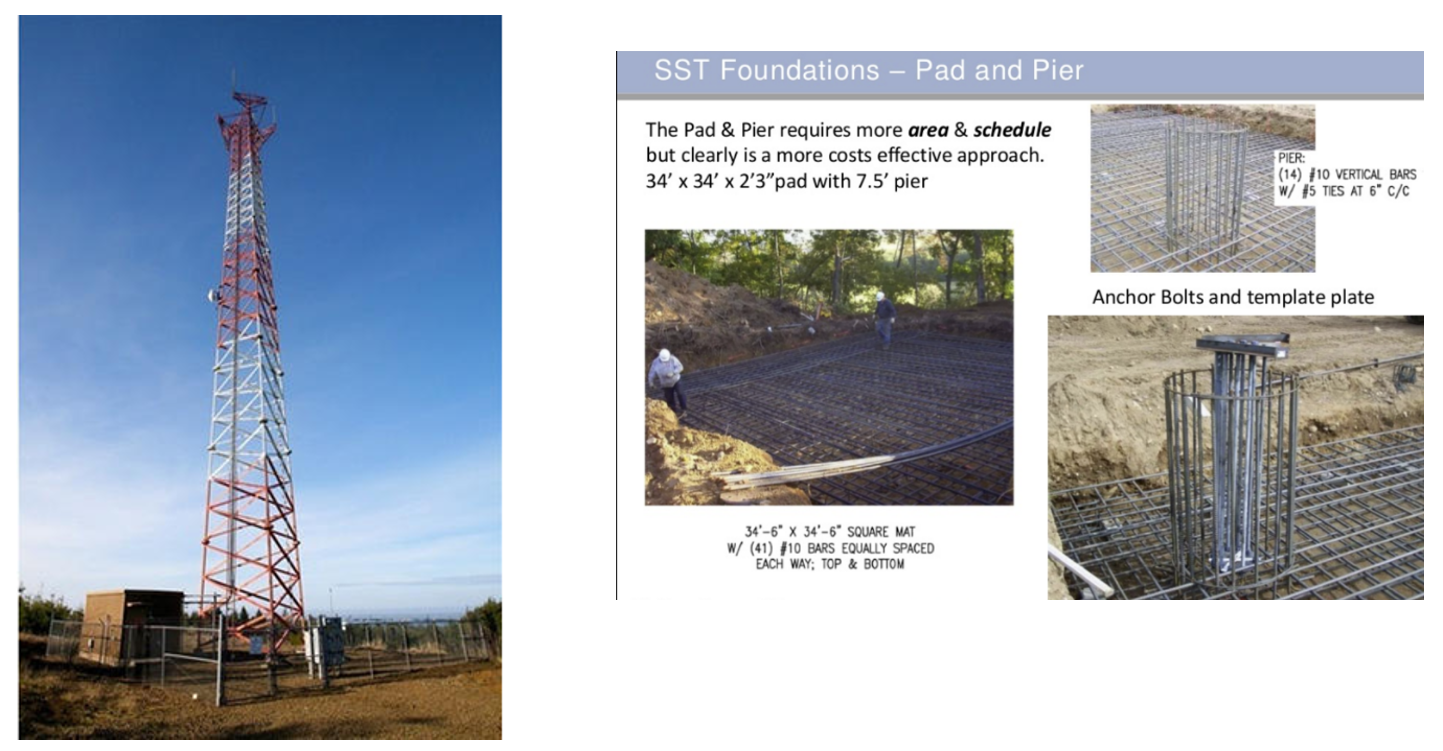
Figure 12. Lattice or Self-supported Tower

Figure 13. Foundation for Lattice Tower (backfilled)
3.1.1.3 Guyed Towers
Guyed towers require larger parcels (for this reason are only possible in rural deployments) but can also achieve greater heights (typically used in TV or broadcast scenarios).
Guyed towers are characterized by getting stabilized by tethered wires. Guyed masts may be in lattice, triangular or square, tapered or straight, as well as monopole structural forms.
There are knock-down guyed tower options that bolts together prior to erection, facilitating tower transportation.
The main advantages of Guyed towers are:
Main characteristics and guidelines for Guyed Towers
Table 7 contains the main characteristics of the Lattice Towers:
|
Main characteristics and guidelines for Guyed Towers |
|
Guyed masts shall be supported and held in position by guy wires or ropes, which shall be made from pre-stretched steel only |
|
The design, based on the load calculations would determine working load and the break strength required of the guy wire and ultimately the choice of the size and grade of the wire. |
|
The choice of each guy earth screw anchor would be dependent on its holding power in the soil, which is a function of its diameter and length to be used to compute the minimum number of guys required. |
|
As a general rule, guys should be planted in three directions at 120 o apart from each other. The distance from the base of the tower to the guy anchor base should be one quarter of the height of the tower. |
|
Guy wires must not be over tightened in the installation of guy towers in order to avoid excessive tension which may cause alignment problems, cable rupture and permanent wrapping of tower structural parts. |
|
All sections must be straight square sections to eliminate potential problems associated with twisting or the need to shim the legs. |
|
Typical tower sections are to have brace configuration with horizontals (z, x or k) and pivot base sections. These tower-structures should be wholly of steel, modular and hot-dip galvanized. |
|
Guyed towers should have tube or solid legs with solid bracing which increases the tower rigidity to allow for the twist and sway. |
Table 7. Guyed Tower Guidelines
The following are descriptive pictures of Guyed Towers:
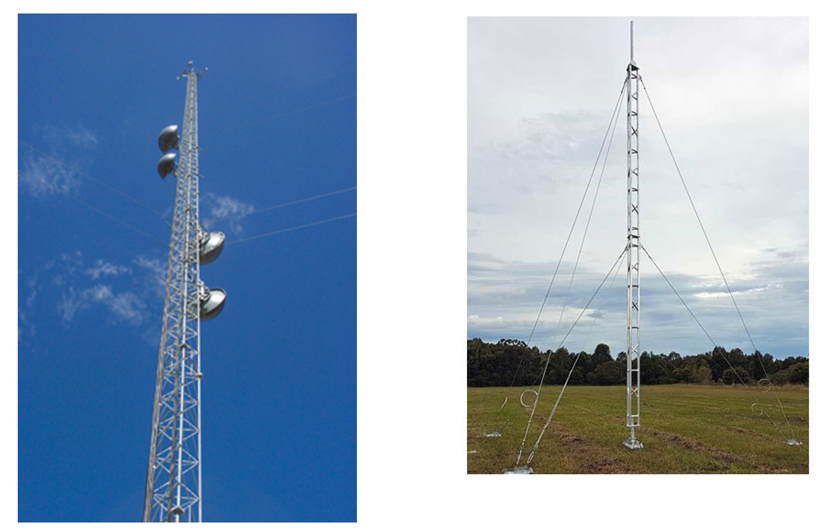
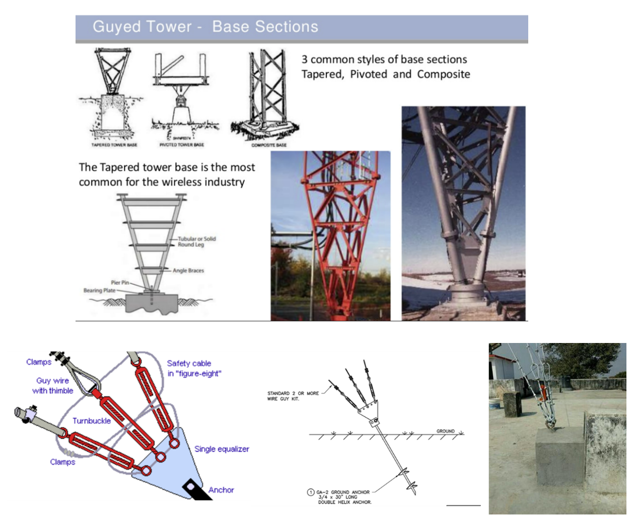
3.1.1.4 Rooftop Structures
Rooftop installations are intended for buildings with a height which is like the average building height in the area they serve.
Buildings too high are normally discarded as they can provoke interference on distant cells and buildings too low are normally discarded due to signal obstruction from the surrounding constructions, which make more efficient the use of street level small cells in combination with alternative rooftops.
Roof mounts are an inexpensive way of elevating signals above the roof or any other obstruction.
Main characteristics and guidelines for Rooftop structures
Table 8 contains the main characteristics applicable to rooftop structures:
|
Main characteristics and guidelines for Rooftop Primary Structures |
|
Structural checks must be made to ascertain the capability of a chosen roof to withstand the additional load being imposed on it by the structure and the entire antenna array it will support. |
|
All Roof mounted towers must be certified by the buildings structural engineer before installation. |
|
As a general rule, roof mounts should be limited to light weight structures of low heights and support minimal dead and dynamic loads. |
|
Roof mounts can be installed in the penetrating or non-penetrating modes and can be self-support or guyed. However non-penetrating roof mounts are most suitable for flat surfaces. |
Table 8. Rooftop Guidelines
The following are descriptive pictures of Rooftop structures:

3.1.2 Antenna Mounting Structures
This section introduces mounting structures used for the different types of Primary structures. Mounting structures will be required for antennas and other equipment to be installed in the tower including Radio Remote Units, solar panels, equipment cabinets and others.
Suitable type of mounting support will be selected according to the antenna or equipment type and the type of tower.
The following are antenna mounting structures used for the type of primary structures described previously in the document.
3.1.2.1 Mounting structures for Monopole Towers
|
Monopole Tower Structure |
|
|
Low Profile Platforms |
|
|
Support Arms for Clamp Rings |
|
|
Monopole Mount for Sectorized Sites |
|
|
Chain Mount Kit |
|
|
Platform with hand rail |
|
|
Universal Clamp Rings |
|


3.1.2.2 Mounting structures for Lattice and Guyed Towers
|
Guyed and Self-supported Tower Structures |
|
|
In Guyed and in Self-supported towers, antenna mounts are attached to a single leg, or across the tower face (leg to leg). Antenna mounts include a) sectored mounting frames b) Face-arm mounts and c) Pipe mounts. |
|
|
Single Leg Sector Mount |
|
|
Face Mount |
|
|
Pipe Mounts |
|

3.1.2.3 Mounting structures for Rooftops
|
Antenna mounts on Rooftops |
|
|
When installing the antenna support on the rooftop, the following guidelines will be followed: ● The strength of the materials for the antenna support and pole should meet the requirements of antenna load capacity and wind load. ● The connecting pieces for the support stiffener should be installed in the positions where the regulation of the antenna orientation and tilt is not affected. ● The antenna support should be perpendicular to the horizontal plane. ● The base of the antenna support, the anchor of the stiffener, and their expansion bolts should be covered with concrete. Ballasts (normally concrete blocks) can also be used to keep mount secure ● If there are enclosing walls on the rooftop, the antenna support can be installed on an enclosing wall. Ensure then that the main supporting post is vertical to the surface of the rooftop. |
|
|
Angle frame with antenna mounting pipes (normally with concrete blocks ballast to keep structure secure) |
|
|
Non penetrating Flat Roof mounts (normally with concrete blocks ballast to keep structure secure) |
|
|
Wall-mount Brackets |
|
|
Pole Wall Mount |
|
|
Wall Mounts |
|


3.1.3 Standards and Regulations
Tower Construction needs to adhere to Standards and Regulations in the areas of:
The Primer of Standard and Regulations: Civil Aviation, Environmental and Radiation Emissions provides detailed information about such Standards and Regulations.
3.2 Cable management construction components
Cable layout are construction components required to manage different type of cabling needs which include:
Depending on the Equipment provider, a solution with hybrid cable solutions is possible, where one or more power conductors and multiple fiber cables are bundled within the same outer jacket. Hybrid cables (power and fiber) are used to connect equipment in the cabinet with active equipment on the tower (such as RRUs or MW outdoor units). Since these cables contain both power and fiber, there is a reduction in the number of individual cables to be run.
The more typical cable management solutions are the following:
Table 9 shows the main construction cable management components:
|
Cable Management Construction components |
|
|
Universal Cable Ladder (Tower applications) |
|
|
Cluster T-Line Brackets (minimize wind load on cables) |
|
|
Waveguide Bridge Channels (Horizontal and Vertical Indoor applications) |
|
|
Waveguide Bridge Support Kits |
|
|
Waveguide Bridge Mount Kits |
|
|
Waveguide Bridge Splice Kits |
|
|
Coaxial Hangers |
|


Table 9. Cable Management Components.
3.3 Power Supply construction components
This Module is not intended to provide guidelines for power calculations to select and dimension the most appropriate power supply source for the site solution. The Civil and Power Design Modules will generate the inputs which will be considered to determine these construction components.
This section describes the construction components required for a proper placement of the elements utilized by the following type of power sources:
Construction components need also to be dimensioned for the required subsystems of these power sources. These subsystems will include AC-DC power rectifiers, DC to DC converters and transfer switches to select alternate or backup power sources.
3.3.1 Power Grid
The following considerations apply to on-grid installations:
For the installations between the electric power meter and the power distribution unit in the equipment cabinet, the main construction components are the following:
|
Power Grid Construction components |
|
|
Galvanized iron conduits |
|
|
HDP Pipelines |
|
|
Register Boxes for Power pipelines installation |
|
|
PVC coated metallic elbows |
|


3.3.2 Solar Panels
Rural installations will frequently utilize solar energy as the main source for site power. Key components of solar systems include Photo Voltaic (PV) panels which absorb and convert shortwave solar irradiance into DC electricity to charge batteries and operate the Site equipment.
In rural environments, these components will typically be placed in the tower itself, and therefore construction components to be considered consist of tower pole mounts to hold these components. For larger sites, it may be required a ground based solar racking system.
|
Solar Power Construction components |
|
|
Typical Rural installation with Solar Panels |
|
|
Tower Mounts for Solar Panels |
|


3.3.3 Batteries
Batteries are typically used as a backup system to allow equipment continuous operation. Batteries contains chemicals that react with one another, producing DC electrical current.
Battery backup times usually range from two to eight hours, depending on the load. When designing the battery capacity, the main power source of the site needs to be considered since it will impact on the required battery autonomy (for example, battery system autonomy should be higher if the power source is solar than if the main power source is the grid).
Low Power installations in rural areas will utilize batteries which will be mounted on towers utilizing universal pole mounting tower accessories and enclosures for batteries. For higher power needs, batteries would be mounted at the bottom of an outdoor equipment cabinet, and for large site configuration options include the usage of self-ballast systems to place the battery banks and optionally also a charge controller to protect the batteries.
Construction components for batteries location must also consider the fact that the batteries can be heavy and use hazardous chemicals.
|
Solar Power Construction components |
|
|
Pole Mounted Solar Systems (low power requirements) |
|
|
Self-Ballast system for Solar Panels and Batteries (large sites with high power requirements) |
|


3.3.4 Diesel Generator
Diesel generators (DGs) are typically used to supply power to cellular Sites deployed in remote off-grid areas. The main issue with Diesel Generators are the high associated operating expenses, which are leading current deployment towards usage of solar systems or hybrid systems utilizing various power source systems.
Most Diesel Generators used in remote rural locations are portable, and then the space is the only item to be considered from a construction point of view. Another option is to use enclosed generator sets, although this option is less practical since it may require an additional concrete pad foundation or structure.
|
Diesel Generator Construction components |
|
|
Portable Diesel Generator |
|
|
Enclosed Diesel Generator |
|


3.4 Equipment Cabinet/Shelter construction components
Different options exist to shelter required equipment in telecommunication sites:
This section will describe the structural options to place equipment cabinets and shelters when they cannot be mounted to towers. These structure components basically consist of platforms and/or concrete bedplates.
Table 10 offers the NaaS Operator with generic guidelines to determine the need for one or more outdoor cabinets space (shelter could be an option if the number of operators in the tower justifies it from an economical point of view):
|
Engineering Area |
Equipment |
Tower mounted |
Shelter/Cabinet |
|
RAN |
RRU |
Yes |
|
|
BBU |
Yes |
Yes (Note1) |
|
|
Transmission MW |
ODU |
Yes |
|
|
IDU |
Yes |
Yes (Note2) |
|
|
Transmission Fiber |
Optical Equipment |
|
Yes |
|
Transmission VSAT |
VSAT |
Yes |
Note3 (Note3) |
|
Power Power Grid |
|
|
Yes (Note4) |
|
Power Solar |
|
Yes |
Yes (Note5) |
|
Power – Batteries |
|
Yes |
Yes (Note6) |
|
Power Diesel Generator |
|
|
Yes |
Table 10. Tower vs Shelter/Cabinet Space Requirements.
Notes:
Note1: RRU in the tower is a current overspread solution, but the possibility to additionally have BBU in the tower will depend on selected RAN Vendor product.
Note2: There are full outdoor MW solutions, but its availability for the MW frequencies to be used will depend on selected Microwave Vendor product.
Note3: VSAT terminal can optionally be mounted to tower or on cabinet.
Note4: To indicate that when Power Grid is utilized, it will require Power Distribution Boards, AC/DC rectifiers, etc. which will usually be installed in an Outdoor Power Cabinet.
Note5: Both Solar Panels and solar controller equipment can be mounted to tower or require ground space depending on the installation power needs.
Note6: There are battery solutions that may be fully mounted in the tower. However, typical solutions may require the usage of an outdoor cabinet for backup batteries.
The following sections introduce the construction components required to place Telecom equipment at the Sites. The considered options are outdoor cabinets and prefabricated shelters, with the preferred option being outdoor cabinets. In case of using an existing Site, it should also be possible to use an existing equipment room to place the new equipment if this room has sufficient space. However, adequacy of a new equipment room would be discarded, since its cost will be higher than the usage of outdoor cabinets.
3.4.1 Outdoor Cabinets
The outdoor cabinet solution will consist of cabinet(s) designed to house equipment.
If installed on a building rooftop, the cabinet will usually be placed on a metallic platform with legs allowing a proper distribution of the load on the columns and beams of the building structure. When installed outdoors, the cabinet will usually be placed on concrete bedplates or metallic platforms. The design of the cabinet allows access to the equipment without the need for the personnel to enter the cabinet.
The outdoor cabinet contains its own controls for heat and air conditioning. Depending on the climatic region, outdoor cabinets could also use passive cooling, resulting in less power consumption and consequent OpEx reduction. In the case that the cabinet was installed indoors (on existing rooms), it could share existing building heat and ac systems.

Figure 14. Outdoor Cabinet and Power Distribution Box on concrete bedplate

Figure 15. Outdoor Cabinet and Power Distribution Box on rooftop platform
3.4.2 Prefabricated Shelters
An alternative to the placement of the RAN equipment is the usage of prefabricated shelters, which size will depend on the equipment racks requirements. This solution shall be considered as the last option specially for rural deployments, and only applied if there is no other feasible alternative.
Telecom shelters are manufactured using either fiberglass, aluminum, or galvanized steel.
The equipment shelter will require the installation of a platform, especially for shelters installed on building rooftops. For shelters installed on outdoor fields, it is also recommended to install the platform on top of a concrete bedplate.

Figure 16. Equipment shelter in rooftop platform
3.4.3 Platforms and Foundations for Equipment Cabinets and Shelters
The following guidelines for platforms and foundations are introduced with the objective to constitute a good reference for a NaaS Operator Construction team for reviewing and assessing the work of the Site Construction Partner.
Equipment Platforms
In the case of rooftop installation of Shelters and/or equipment Cabinets, it will be required to install a platform. These platforms will allow the distribution of the load on the columns and beams of the building structure.
In case of outdoor deployments, cabinets or shelters will be place on top of a concrete foundation or on top a platform (platform will be placed on compacted earth).
Equipment Platforms should be made of hot dip galvanized steel with adjustable legs.

Figure 17. Equipment Shelter and Tower on platform
Foundation Requirements
A concrete foundation is typically used for outdoor shelter installations.
Foundation design for prefabricated shelters and other equipment must be based upon site soil conditions as noted in the geotechnical report. These foundation plans must be designed by a licensed Professional Engineer and the design must be included in the Site Engineering document.
A Professional Engineer or contracting firm should determine whether the soil is adequate to properly support the concrete foundation or slab. The Professional Engineer or contracting firm should determine the excavation depth and the required fill, if required.
Foundation design should consider any precipitation conditions unique to the location. These considerations include (but are not limited to) elevated (pier type) platforms used in low-lying areas prone to regular flooding, and elevated foundations used to prevent burial of site due to snowfall.
All foundation construction must be performed by a qualified contractor specializing in this work.
3.5 Site Grounding and Lightning construction components
Towers are structures with a high risk of lightning strike and therefore require lightning protection systems. The essential function of a lightning protection system is to prevent lightning strike damage to structures and equipment. Lightning and grounding system allow diverting the strike energy to the ground bypassing the equipment and thus preventing it getting damaged.
Vendor Construction Vendors must provide a certified grounding solution for each one of the configurations required by the NaaS operator, considering the differences in the grounding system design. Different grounding system design is needed for solutions where all the equipment is mounted to the tower versus solutions where outdoor cabinets or shelters are used.
3.5.1 Grounding in Tower Sites
The section contains the main aspects to be considered for Tower sites grounding.
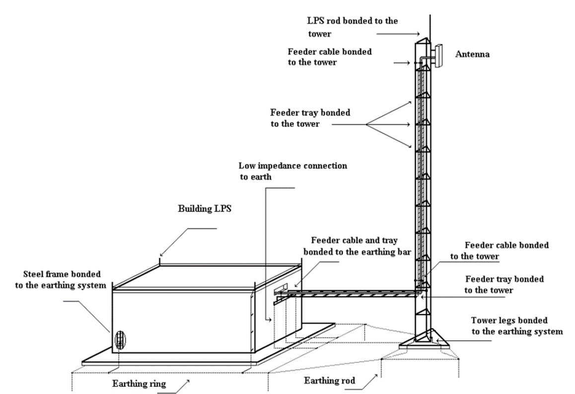
Figure 18. Tower Site Ground and Lightning Protection System
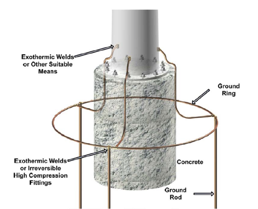
Figure 19. Illustration of monopole tower grounding example
Variations to the grounding layout scenario described above are possible when all the equipment is installed at the tower or when space constraints do not allow for a ring that encircles the entire structure. In this case:
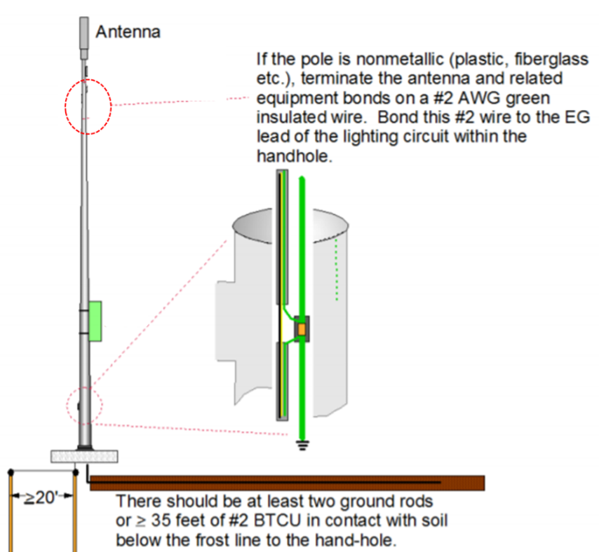
Figure 20. Pole Ground System
The measurement of earth resistance is made by the potential fall method. The resistance area of the earth electrode is the area of the soil around which a voltage gradient is measured with a commercial instrument. In the figure shown below E is the earth electrode under rest, and A is an auxiliary earth electrode positioned so that two resistance areas do not overlap. B is the second auxiliary electrode which is placed between E and A.

Figure 21. Measuring Earth resistance
An alternating current of steady state value passes through the earth path from E to A and the voltage drop between E and B is measured:

The electrode B is moved from position B1and B2respectively so that the resistance area do not overlap. If the resistance values determined are of approximately the same in all three cases, the mean of the three readings can be taken as the earth resistance of the earth electrode.
The auxiliary earth electrode A must be driven in at a point further away from E and the above test repeated until the group of three readings obtained are in good agreement.
3.5.2 Grounding in Rooftop Sites
Rooftop sites, and sites where equipment is located inside a host building, require unique site by site grounding and lightning protection design considerations.
The grounding design will be adapted according to the following items:
The grounding system of the Site consists of the interior ground system (when there exists an equipment room) and the outdoor grounding system.
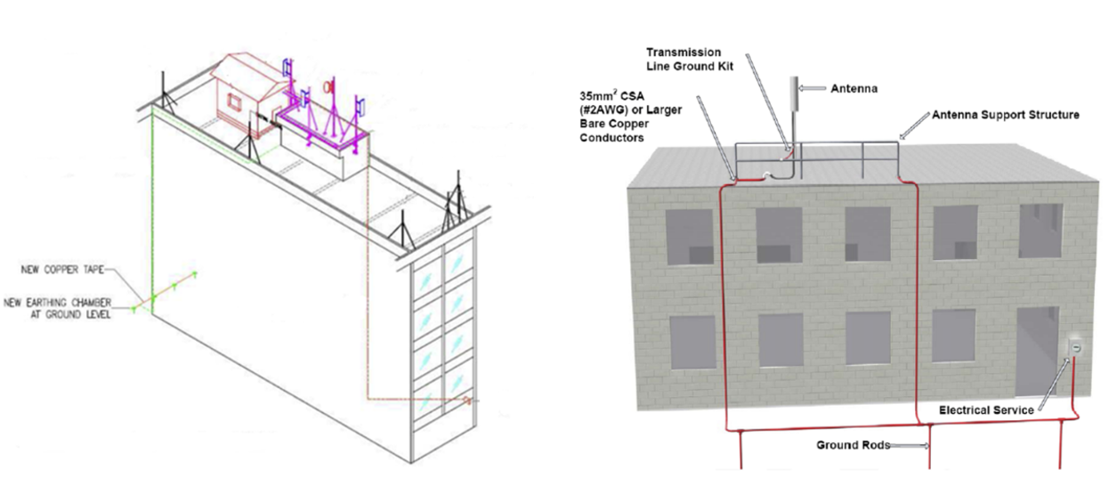
Figure 22. Illustrative view of roof mounted grounding installations
3.5.3 Grounding construction components
Table 11 shows construction elements used for grounding systems:

Table 11. Grounding Construction components.
4 Vendor Evaluation and Selection
This section offers the NaaS operator a methodology and approach to select Vendors to provide Site Construction site solutions and construction services.
The selection of the appropriate Vendors for Site construction projects requires conducting a RFI/RFP (request for information and proposal) process which analyzes the contractor ability to fulfill the end-to-end tasks and also obtains pricing information to fulfill the required Construction Solutions and Services.
Please note that the Site Construction RFI/RFP process benefits from the framework setup established in the generic RFx Process Module. It is recommended to go through the RFx process module if further details are required regarding the process. The RFx Process Module provides a general overview of the end-to-end RFx process including the description of the activities which take place for RFx development:
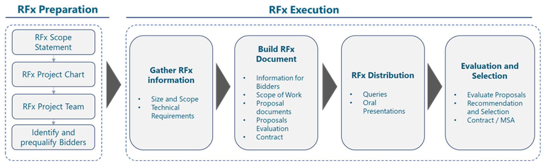
Figure 23. RFx process
RFx are issued to obtain Information, Proposals or Quotes from the market. RFx processes play an important role in the NaaS Operator organizations, who require the procurement of products and services from external vendors. In order to obtain truly valuable and effective information from these processes, the documents generated during the RFx development must include all the relevant information that Respondents will require to provide accurate responses to the NaaS Operator request, avoid misunderstandings and prevent implementation issues.
The RFx document must clearly identify the RFx objective (obtain information, proposal and/or quotes), the scope of the technical project, the instructions to respond and applicable terms and conditions.
The Site Construction RFI/RFP document Template provided as an addendum to this document goes through the areas in the RFx structure described above.
The RFI/RFP document Template includes a set of Site Construction solutions as part of the requirements to the Bidders in the Scope. The NaaS Operator can adapt the Scope to the Site Configurations which best suites their specific type of deployment.
In the case of the Site Construction process, the following figure illustrates specific considerations to be applied to the generic RFI/RFP structure:
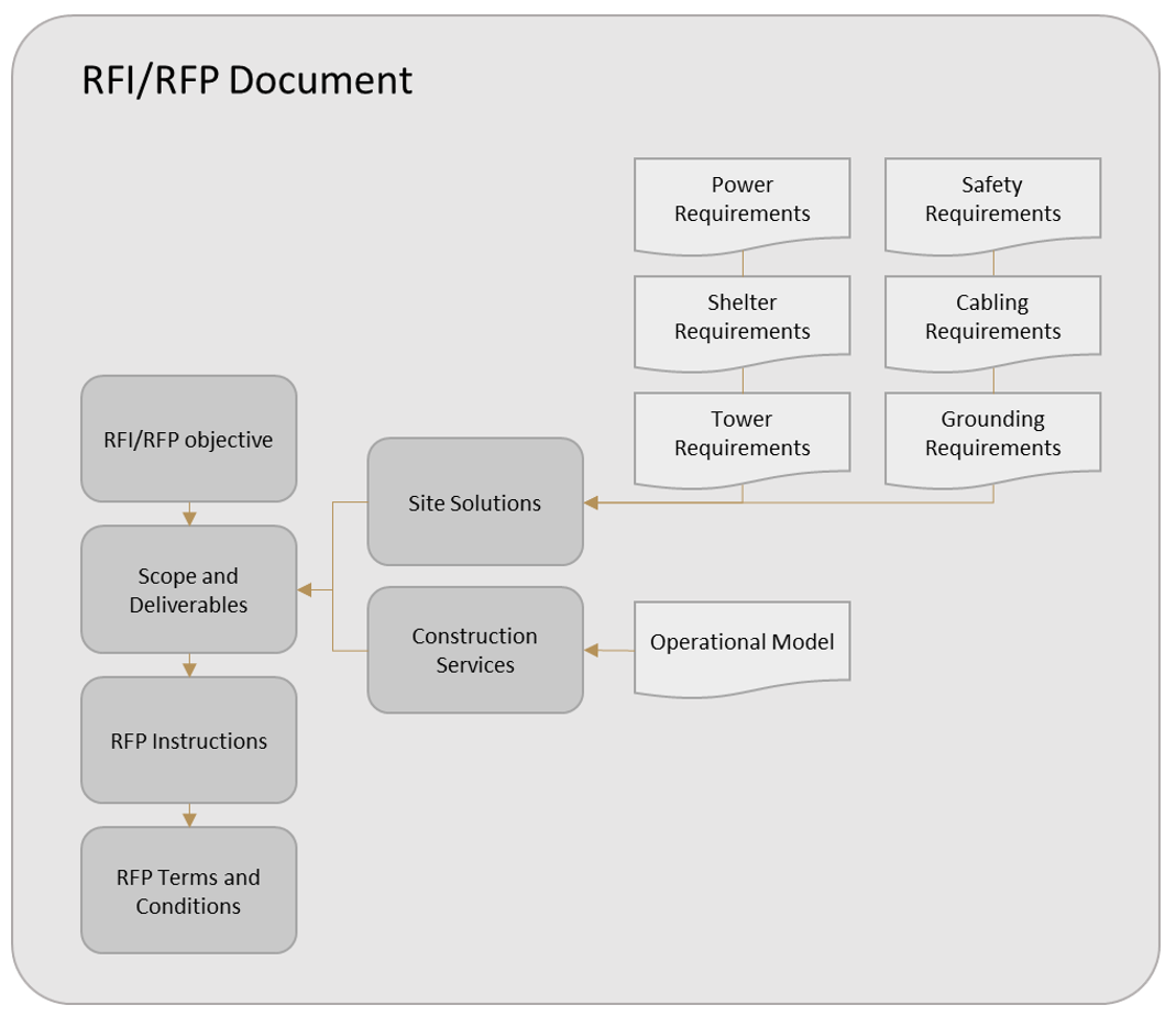
Figure 24. Site Construction RFI/RFP Document areas
Before starting the RFI/RFP process, it is necessary to select the companies which will be receiving the documentation. The following sections provide instruction to select, invite and prequalify potential Bidders for the process.
4.1 Site Construction RFI Target Market
The first step is to identify potential contractors to which the Site Construction RFx should be addressed, with an eventual invitation to bid.
The NaaS should invite contractors with previous and successful experience with the company and their competitors. In absence of previous references, options may include web research as well as requesting a list of Site Construction potential partners to local partners and authorities, local Chambers of Commerce and professional associations.
The potential Respondents shall be sent an invitation letter, an abstract of the project scope and relevant RFx dates, and a prequalification form.
4.1.1 Invitation to tender
The NaaS Operator shall submit an invitation to tender to the identified companies to inform about:
The objective of the formal invitation is to inform Bidders of commencement of the RFx process.
4.1.2 Pre-qualification form
Potential Respondents shall receive, together with their invitation to bid, a prequalification form.
This form provides key questions which the NaaS Operator will use to determine the suitability of the potential respondent to address the project scope. This qualification form includes questions in the areas of Finance, Quality Management, CSR&EHS (Corporate Social Responsibility & Environment, Health and Safety) and Site Construction implementation experience. The template will assign points based on those responses and will provide an overall score that can be used to rank the candidate vendors.
NaaS Operator can use the Site Construction pre-qualification template for this purpose. This document allows identifying the main capabilities of the vendors, and discards those without the technical or financial capabilities to fulfill the project requirements.
4.2 RFx Document
Having selected the candidate vendors through the pre-qualification process, the vendors shall enter an RFx process which is described in detail in the RFx Process module.
The RFx document identifies the RFx objective (obtain information, proposal and/or quotes), the scope of the technical project, the instructions to respond and applicable terms and conditions.
The Site Construction RFI/RFP Template provided as part of the PlayBook covers the areas in the RFx structure described above. This document must be adapted by the NaaS Operator to the site construction specifics of the project.
4.3 RFx Evaluation Process
The Site Construction RFI/RFP Template provides additional information on the inputs required to perform a response evaluation. Further details and general procedures on evaluation criteria are included in the RFx Management Module.
The evaluation process must be based on fair competition, with mandatory and optional requirements being clearly identified and properly notified to the bidders. The scoring model must be closed before the commencement of the analysis and, if by any reason it must be modified during the RFQ process, bidders must be notified and given the opportunity to amend their proposals.
The evaluation process as well is further developed in the RFx Process module and is considered out of the scope of this document.
5 Vendor Management
Once Site Construction Vendors have been selected using the RFI/RFP process described in the previous section and the contract for Services has been agreed and signed with them, NaaS Operator will be ready to start with the execution of the contract. The execution of the contract with selected Site Construction Vendors will require the NaaS Operator to execute activities to manage the selected Vendors and their performance.
Site Construction Vendors management will start with the on-boarding of selected contractors, and will include activities to produce the project plan, track the performance of their activities and finally accept the construction of each Site. These Vendor management activities are described in the following sections.
5.1 Vendor On-Boarding: Kick-Off Meeting
Vendor On-Boarding will commence with the Kick-Off meeting, which will be triggered by the conclusion of the contracting process.
Therefore, the Kick-off meeting will be held with Vendor representatives responsible for the Site Construction process. It will be a NaaS Operator decision if maintaining individual meetings with each Site Construction Vendor or a collective meeting with all of them.
It could be the case that a Kick-off meeting is held with all selected Construction Vendors or only with those who will start implementing Site Construction activities at the beginning of the Project. This will depend on the Project Plan developed by the NaaS Operator.
5.2 Vendor Management: Lead Times and Project Plan
NaaS Operator will share the objective Project Plan with the Site Construction Vendors. The Project Plan will show the number, the distribution in phases and the geographical distribution of the Sites to be built.
The Project Plan will establish the Baseline of the Project. All Rollout Progress Reports will compare the current situation versus the established Project Plan.
The Project Plan will be based in the application of agreed Lead Times. Lead Times will show information about the elapsed time for each (or main) construction activities. Lead Times will have already been agreed with Construction Partners in the contracting phase, to determine their capability to respond to the Plan.
Developing the NaaS Operator Construction Project Plan will consider a set of Lead Times for each construction activity. These activity durations will be adapted by the NaaS Operator depending on the specifics of the Project Scope and based on the agreements reached with the Construction Partners.
The duration of the activities could vary significantly depending on the selected type of towers or primary structures and the required needs for associated construction works. Table 12 provides an activity breakdown and reference activity durations for the Site Construction. NaaS Operators can use the Gantt diagram for Site Construction template to prepare its customized Project Plan:
|
Task Name |
Duration (days) |
|
Site Survey and A&E Analysis |
18 |
|
Technical Site Survey (preparation and generation of report) |
4 |
|
Engineering and Structural Evaluation |
14 |
|
Construction |
35 |
|
Soil excavation and ground cleaning |
2 |
|
Stoke and leveling |
1 |
|
Excavations for base and tower |
2 |
|
Steel assembling and leveling |
3.5 |
|
Dice shoring |
2 |
|
Bending concrete basis for equipment |
2 |
|
Concrete casting |
1 |
|
Base filings and compacting |
2 |
|
Main Power Installation |
3 |
|
Main Power connection |
2 |
|
Tower erection |
4 |
|
Rebuff enclosure bases assembling |
2 |
|
Perimeter Fence/wall installation |
3 |
|
Access door assembling |
0.5 |
|
Preparation of electrical and ground canalization |
2 |
|
Electrical and grounding registers installation |
2 |
|
Application of Gravel |
1 |
Table 12. Construction Tasks Estimated Duration.
5.3 Vendor Management: Reporting and Milestone Tracking
Site Construction Reporting will be oriented to show the current Construction progress (current status) versus the Baseline Timeline (Project Plan). Reporting will allow the NaaS Operator to understand the differences in the Timeline, report accomplishment of Process Milestones and description of Risk items which are impacting the Project timeline.
NaaS Operator will define the Governance methodology for Vendor Management. The specific Project will determine the required adjustments to be implemented to adjust the periodicity and content of the reports. The following are the suggested guidelines for Site Construction Vendors Management:
|
Item |
Description |
|
Project Tracking File |
The Project Tracking file is a master Excel file containing the details required for reports development. It includes main milestones and related accomplished dates and it will require Construction Vendors to access and update accordingly. This module includes a Site Construction Milestones tracking template, which can be used by the NaaS Operator as the file to track main milestones of Vendor construction activities. This Project Tracking file could be replaced by a Project Management software solution which could be enhanced with an Inventory Solution. |
|
Monthly Report |
Excel and PowerPoint files with the number and critical route of the project status and big milestones |
|
Weekly or Daily Report |
Excel File with comparison between Baseline, forecast and actuals date and accomplishment of the project milestones. Identification and description of risks impacting the timeline. |
Main Milestones that will be tracked in the above mentioned Progress Reports include the following ones:
|
Milestone |
Description |
|
Technical Site Survey Report Ready |
After the Technical Site Survey has been completed, Vendor will be responsible for delivering the Technical Site Survey Report. Please refer to Section Technical Site Survey and Technical Site Survey template (template A) for information to be included in this Report. |
|
Site Engineering Document Ready |
Once Structural Analysis of the Site solution has been performed (if/when required), Vendor will prepare the Site Engineering Document with the level of detail agreed with the NaaS Operator. Site Engineering Document will be validated by NaaS Operator as the official document of the Site solution to be built. Please refer to Section Architecture and Engineering Analysis for information to be included in this Document. |
|
Site Construction Work Order Ready (or Ready For Construction) |
Site Construction Work Order will be released by NaaS Operator to authorize the initiation of Site Construction (or Ready For Construction Milestone) |
|
CW Completed (Civil Works completed) |
This Milestone will indicate the finalization of Construction Works. If project specifics make it necessary, the CW completed Milestone could be divided into: ● Civil Works Ready: indicating that Site preparation and foundations have been completed. ● Mechanical Works Ready: indicating that tower and equipment shelter have been erected, as well as antenna mounts and cable construction components. ● Electrical Works Ready: indicating electrical and ground canalization has been prepared and electrical and grounding works have been completed. |
|
Site Construction Acceptance |
Once Construction is finished, Site Construction Vendor will notify the NaaS Operator that the Site is Ready for Civil Engineering Acceptance. NaaS Operator will then execute an Acceptance of the Civil Works and issue the Site Construction Acceptance if any items need to be repaired. To perform the Site Construction Acceptance, NaaS Operator (or designated 3rd party company) will utilize the Site Construction Acceptance Checklist template. In the Site Construction Acceptance Form, NaaS Operator will determine all the construction items that need to be fixed (punchlist) by Site Construction Vendor before issuing Site Construction Acceptance. |
|
Ready For Installation |
Once the Site Construction Vendor has fixed all the items in the Punchlist, it will notify the NaaS Operator that the construction activities have been finalized and the Site is ready for Equipment Installation. |
5.4 Vendor Management: Site Construction Acceptance
Site Construction Vendors will notify NaaS Operator that Site Construction has been completed and is Ready for Site Acceptance. NaaS Operator representatives will then conduct a Site Condition assessment utilizing a Site Construction Acceptance Checklist.
NaaS Operator representatives will use this Checklist to indicate the punch items that need to be fixed by the Site Construction Vendor, including all the necessary descriptive comments and photographs of the structures to highlight such items.
NaaS Operator can utilize the Site Construction Acceptance Checklist template provided as part of the Runbook, which is based in the information contained in the ANSI-TIA/EIA-222 standard (Structural Standard for Antenna Supporting Structures and Antennas).
Vendors will also be responsible for providing all required documentation needed during the Site Construction process.
All documentation will be made available to the NaaS Operator in the designated document repository and inventory systems as required.
Site Construction documentation will include among other documents the Technical Site Survey report, Site Engineering document, Site As-built document and the Site Construction Acceptance checklist.
Network Inventory system will allow the NaaS operator to capture in a shared and centralized platform all the details of the physical site infrastructure resulting from the site construction activities.